Flexible Printed Circuits
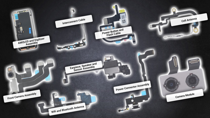
As the name implies, a flexible printed circuit, or “FPC,” is a circuit board that is flexible and can be bent, twisted and even folded to a certain extent. By comparison, the more familiar type of PCB, a rigid PCB, cannot be bent, twisted or folded. FPCs can be used in a countless number of applications and are having a dramatic effect on the digital transformation of practically every aspect of our lives. For example, they can help continue the trend of consumer electronics becoming even smaller, more powerful and more useful, such as with bendable smart phones. FPCs are important for the automotive industry as cars become more automated. They’re also critical in the medical and healthcare fields, as they can, for example, advance implantable and wearable device capabilities. And with the rollout of 5G and the Internet of Things, the demand for FPCs will grow even further. This is just a portion of the applications and industries that FPCs can be used in, as they can also be used extensively in aerospace, robotics, AR/VR and many others.
Lasers and Processing of FPCs
Lasers are widely used in the processing of flexible circuit boards for operations such as singulation, or depaneling, coverlay patterning, and drilling holes and vias. But, not all lasers are the same.
UV Short-Pulse Lasers Provide Advantages over CO2 Lasers
The optimal lasers to use for FPC processing are UV, or ultraviolet, wavelength lasers with short pulses and high repetition pulse rates. Shorter laser wavelengths allow smaller beam spot sizes and tighter focusing, which is beneficial for FPC processing in a number of ways:
- Higher precision operations
- Achieve smaller dimensions for even more flexibility and miniaturization
- Less material wasted, allowing more circuits to fit on a panel
Such results are not possible with longer-wavelength lasers, such as CO2 lasers. Only the tighter focus provided by shorter wavelength UV lasers provide beam spot sizes sufficiently small for drilling the required hole dimensions that will enable further miniaturization of FPCs.
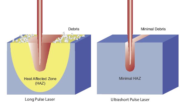
Lasers with short pulses and, in combination, higher repetition rates are advantageous because in general, the shorter, or faster, the pulse, the higher the quality of a cut or drill will be. Shorter pulse widths can deliver intense peak powers resulting in:
- Nonlinear absorption at the sample for instantaneous material vaporization
- Very minimal heat transfer into the material
- Much smaller heat-affected zone, or HAZ
- Higher throughput and fewer part failures
While most commercially available pulsed CO2 lasers have pulse widths in the millisecond or microsecond range and repetition rates up to a few hundred kHz, by contrast, Spectra-Physics UV diode-pumped solid state lasers feature pulse widths in the nanosecond range and rep rates up to 500 kHz.
Another feature that can be provided by Spectra-Physics UV diode-pumped solid state lasers is high power. This allows faster operations, such as cutting, which results in higher yields and meeting the throughput requirements for FPC processing. At the same time, it is important to note that the quality of the operation will not be sacrificed for speed due to the benefits provided by the shorter pulse widths and high repetition rates.
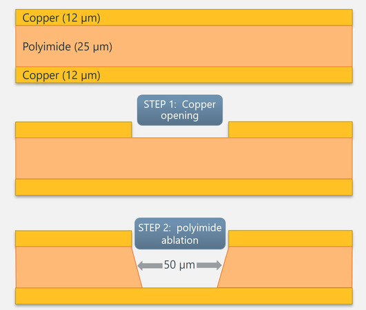
UV wavelengths also contribute to efficient processing, as they are well absorbed by a variety of materials in FPCs, including copper and polyimide. Thus, the high beam intensity with smaller beam spot sizes achievable with UV wavelengths that Spectra-Physics lasers offer can efficiently remove copper, while a lower beam intensity with the same type of laser can cut dielectric material without damaging the bottom copper layer.
MKS Solutions for Flexible Printed Circuit Processing
MKS has many solutions to help meet the current and future flexible printed circuit board manufacturing challenges.
The first challenge that often comes to mind is maximizing throughput and yield. MKS offers UV and green short-pulsed lasers, including high power lasers with pulse control, that can be used for singulation or depaneling, coverlay patterning, and drilling both blind via holes and through-vias. We believe that UV lasers are superior to longer-wavelength CO2 lasers for FPC processing. To ensure that the laser system is performing optimally, MKS offers fast laser measurement and profiling instruments. To manage the high power lasers, MKS also provides high power/high fluence optics for optimal results. And to position components for a process quickly and accurately, MKS can provide high-speed, high-precision motorized positioners.
Another challenge is to improve the quality and reliability of FPCs. Our nanosecond and ultrafast lasers can provide the cleanest cuts and drills with the least amount of thermal and other damage, leading to higher quality and reliability. Additionally, MKS' optical mounts are very robust and stable, so that laser performance will not decline easily over time.
As flexible circuit boards are becoming more and more miniaturized, drilling vias, depaneling and coverlay patterning all become more challenging. The smaller beam spot sizes enabled by the short wavelengths of UV lasers that MKS provides can meet the smaller dimensional requirements presented by miniaturized FPCs.
| Challenges in Flex Circuit Manufacturing | MKS Solutions |
|---|---|
| Maximizing throughput & yield | UV short-pulsed lasers for high speed, yield and precision micromachining Fast, high power laser measurement and profiling High power/high fluence optics to manage the lasers High speed and precision motorized positioners |
| Improving quality and reliability | Nanosecond and ultrafast lasers for highest quality micromachining Robust, stable optical mounts |
| Miniaturization of FPCs | UV lasers for smaller beam spot sizes |
Your Partner for Flexible Printed Circuit Processing
- 50+ years and thousands of alignment systems for optical applications
- Long-term partner to semiconductor manufacturing companies
- Full range of products: lasers, optics, motion, opto-mechanics, beam analysis
- Custom capabilities
- Product availability
- Ability to scale with you
- Global corporation and presence
 Lasers |
 Beam Analysis |
 Motion Control |
 Opto-Mechanics |
|---|---|---|---|
|
|
|
|
Lasers
Criteria for Selecting Lasers
- Application Requirements
- Function
- Type of Material & Thickness
- Speed
- Resulting Size of Heat Affected Zone (HAZ)\
- Laser Specifications
- Wavelength
- Power
- Pulse Width & Repetition Rate
- Stability
- MKS Laser Applications in FPC
- Hole and via drilling
- Singulation (depaneling)
- Coverlay patterning
Lasers for Flexible Printed Circuits
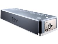
- Talon® Nanosecond Lasers: superior combination of performance, reliability and cost.
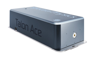
- Talon® Ace™ Laser: highest single-mode ns UV power in the industry, with TimeShift programmable pulse capability
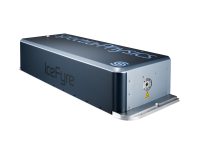
- IceFyre® Picosecond Lasers: exceptional performance and unprecedented versatility at industry-leading cost-performance
 Talon |
 Talon Ace |
 IceFyre |
|
|---|---|---|---|
| Wavelengths | UV or Green | UV | UV |
| Power | UV: Up to >45 W Green: Up to >70 W |
>100 W | Up to >50 W |
| Pulse Width | UV: <25 or 40 ns Green: <25 or 43 ns |
<2 to >50 ns | <12 ps (10 ps typical) |
| Repetition Rates | 0 to 500 kHz | Single shot to 5 MHz | Single Shot to 10 MHz |
| Max Pulse Energy | UV: Up to >500 µJ Green: Up to 1000 µJ |
Up to >500 µJ | Up to >60 µJ |
| Other Features | Laser/controller in single, compact package 24/7 industrial reliability E-Pulse™ technology for superb stability |
24/7 industrial reliability TimeShift™ technology for pulse control Laser/controller in single, compact package |
24/7 industrial reliability TimeShift™ technology for pulse control Laser/controller in single, compact package |
Flexible Printed Circuit Laser Selection Guide
Presented here is a summary of recommended lasers for various flexible PCB manufacturing applications. Please use this as a reference guide only, and always contact us to discuss your application and requirements in detail so that we may provide the best solution for you.
| Talon® | Talon® Ace™ | IceFyre® | |||
| Speed / Throughput | ✓✓ | ✓✓✓ | ✓✓ | ||
| Quality of cut or drill (HAZ, burrs, residue) | ✓ | ✓✓ | ✓✓✓ | ||
| Operational Flexibility | ✓✓ | ✓✓✓ | ✓✓✓ | ||
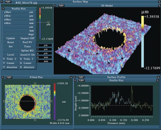
| Blind via drill examples Left: Entrance of hole Right: Bottom of hole |
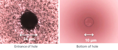 Entrance = 24 µm, Exit = 10 µm Entrance = 24 µm, Exit = 10 µm |
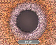 Entrance = 50 µm Entrance = 50 µm |
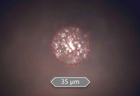 Exit = 35 µm Exit = 35 µm |
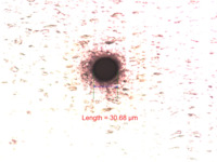 Entrance = 30 µm Entrance = 30 µm |
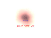 Exit = 20 µm Exit = 20 µm |
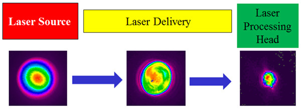
Laser Beam Analysis
Even with the advantages that lasers have over traditional tools, laser systems can still degrade over time. Some causes of degradation include thermal effects on a laser system’s internal components, vibrations or shock and debris near the processing site. These issues could affect laser performance in a number of ways. First, output power may be reduced, causing the laser to be less efficient. Another problem that may be caused is a change in the focus or other profile of the beam, which may lead to a cut or drill to be off target, too deep, low quality or possibly damaging to another part of the material.
Therefore, to ensure the highest quality flexible printed circuits manufacturing and to minimize the possibility of production down-time, it is crucial to monitor the laser beam frequently with appropriate instruments–like Ophir® power sensors, power meters and beam profilers–that can operate at the laser’s wavelength while handling its maximum output power level.
Causes of Laser System Degradation
- Thermal Effects
- Debris from Process
- Vibrations and Shock
Criteria for Beam Analysis Instruments
There are three types of beam analysis instruments to monitor your laser: (1) sensors and detectors to measure power, (2) power meters to process the information provided by sensors and (3) beam profilers to determine focus position and other beam characteristics. Shown below are the main criteria for choosing such instruments.
Laser Sensors- Compatible with laser wavelength
- Power/energy range/density
- Beam size
- Calibrated power measurement
- Compatible with sensor
- Connect to system/PC
- Track process data over time
- Compare multiple measurements at once
- Measurement of multiple attributes
- Focal shift
- Focal spot size
- Laser power and power density
- Changes over time
- Laser propagation characteristics
- Speed of measurement
Laser Power Sensors
MKS offers a comprehensive portfolio of Ophir® laser thermal power sensors, several of which can measure the optical output power of short- and ultrashort-pulsed lasers such as IceFyre, Talon, Talon Ace and Quasar. These sensors have a very high damage threshold to withstand the high optical peak power delivered by each pulse. Ophir sensors and meters meet the ISO/IEC 17025 standard for calibrated devices.
- Laser Thermal Power Thermal Sensors: very high damage thresholds for hundreds of watts power measurement.
| F150(200)A-CM-16 | 30(150)A-SV-17 | F80(120)A-CM-17 | ||
|---|---|---|---|---|
| Spectral Range | 0.248-9.4 µm | 0.19-11 µm | 0.248-9.4 µm | 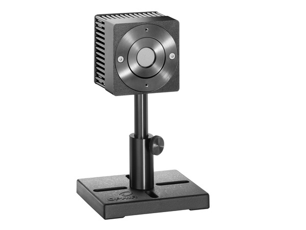 |
| Power Range | 300 mW - 200 W | 100 mW - 150 W | 100 mW - 120 W | |
| Energy Range | 50 mJ – 200 J | 50 mJ – 300 J | 50 mJ – 200 J | |
| Max Avg Power Density | 35 kW/cm2 | 60 kW/cm2 | 35 kW/cm2 | |
| Max Energy Density (2 msec) | 45 J/cm2 | 50 J/cm2 | 45 J/cm2 | |
| Aperture | Ø16 mm | Ø17 mm | Ø17.5 mm | |
| Response Time | 3 sec | 1.7 sec | 2 sec | |
| Other Features | Not water-cooled | |||
Power Meters
Ophir laser power and energy meters work on the smart plug principle. This means that almost any power meter can work – plug and play – with almost any of the wide range of Ophir optical sensors.
| Power Meters | Virtual Power Meters | ||
|---|---|---|---|
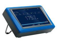 Centauri |
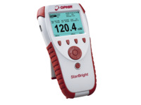 StarBright Handheld |
 Juno+ |
 EA-1 |
|
|
|
|
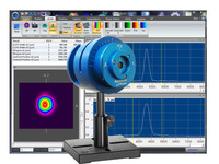
Beam Profilers
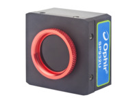
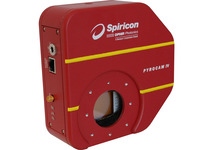
An effective way to analyze beam profile is with a camera-based system. Ophir beam profiling cameras allow real-time viewing and measuring of a laser’s structure in high resolution. Camera-based systems can also measure cross-sectional intensity of the laser and provide a complete 2-dimensional view of the laser mode.
- SP932U Beam Profiling Camera: high resolution, real-time viewing and measuring of laser structure with highest accuracy in the industry
- Pyrocam™ IV Beam Profiling Camera: generates full 2D profiles of CO2 and NIR lasers in CW or pulsed modes of any frequency
- NanoScan™ 2s Pyro/9/5 Scanning-Slit Profiler: sub-micron precision for generating 2 orthogonal linear profiles of a CO2 or IR beam
 SP932U |
 Pyrocam™ IV |
 NanoScan™ |
|
|---|---|---|---|
| Spectral Range | 190-1100 nm | 13-355 nm, 1.06-3000 µm | 190 nm-100 µm |
| Power Range | 5 mW to 100 W | ||
| Damage Threshold | 50 W/cm2, 1 J/cm2, <100 ns pulse width | 2 W over entire array, 20 mJ/cm2 (1 ns pulse) | |
| Beam Sizes | 34.5 µm to 5.3 mm | 1600 µm to 25.4 mm | 20 µm to 6 mm |
| Pixels | 2048 x 1536 Effective Pixels, 3.45 µm Pixel Size | 320 x 320 Effective Pixels, 75 µm Pixel Size | |
| PC Interface | USB 2.0 | GigE | USB 2.0 |
| Other Features | BeamGage® software included UltraCal™ correction algorithm Measures cross-sectional intensity 72 dB true dynamic resolution 24 Hz frame rate in 12-bit mode |
BeamGage® software included CW or pulsed beams Measures cross-sectional intensity |
Graphical user interface software included CW or >25 kHz pulsed beams |
Motion Control
Galvanometer Scanners and Linear Positioners
- Advantages
- Used to steer laser
- Fast scanning (meters/sec) with sharp corners
- Limitations
- Limited field of view (~100-200 mm)
- Limited focal spot size (10-20 µm)
- Advantages
- Used to position galvo(s)
- Large field of view
- Allows tight focal spots (<10 µm)
- Limitations
- Not as fast as galvos
Combined Galvo-Linear Positioners System
- Combines speed of galvos with FOV allowed by positioners
- Galvo and positioners can be synchronized with advanced motion controller
- Enables "stitching":
- Galvo process for "cells"
- Positioners place next cell as target
- Repeat galvo process
| Galvos | Linear Positioners | Combined System | |
|---|---|---|---|
| Speed & Acceleration | Fast | Not as fast | Fast |
| Field of View (FOV) | Limited | Large | Large |
| Focal Spot Size | Limited | Tighter | Tight |
- MKS offers a full range of positioners and motion controllers
- Galvos purchased separately – MKS controllers can interface with galvos
Guaranteed Motion Control Performance
- Stages that MKS ships meet or exceed the guaranteed specifications
- Metrology reports included with each stage (ASME B5.57 and ISO 230-2 standards)
- Typically, the product will perform ~2x better than the guarantee
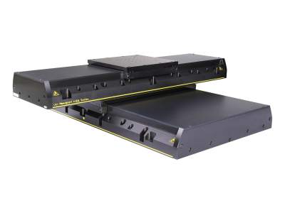
IDL-LM Series Linear Motor Positioners
Highest load capacity and speed of all linear motor positioners for demanding production environments
| Travel Range | 100 to 1,200 mm |
| Speed | 2 m/sec |
| Load Capacity | 450 to 200 N |
| Pitch | ±15 to ±65 µrad |
| Yaw | ±15 to ±40 µrad |
| Accuracy | ±2 to ±5 µm |
| Other Features |
Ironless Linear Motor Recirculating ball bearings Industrial grade hard covers |
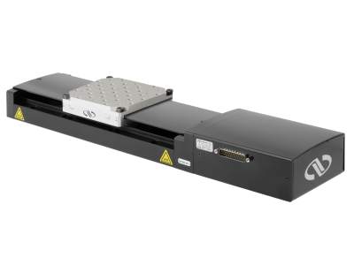
IMS Series Long-Travel Aluminum Linear Positioners
High load capacity, long travel, fast movement capable of high-duty cycles in industrial applications
| Stepper Motor | DC Motor | |
|---|---|---|
| Travel Range | 300 to 600 mm | |
| Speed | 100 m/sec | 200 mm/sec |
| Load Capacity | 600 N | |
| Pitch | ±37 to ±50 µrad | |
| Yaw | ±15 to ±30 µrad | |
| Accuracy | ±2.5 to ±4 µm | |
| Other Features | Double-row recirculating ball bearings Linear motor version available |
|
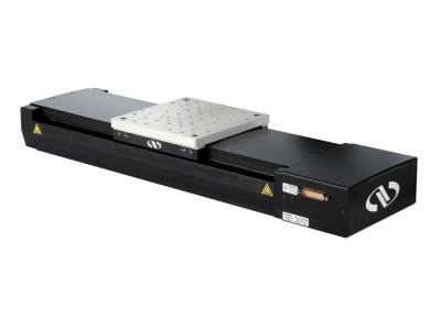
ILS Series Mid-Travel Aluminum Linear Positioners
High load capacity, mid-travel, fast movement capable of high-duty cycles in light industrial applications
| Stepper Motor | DC Motor | |
|---|---|---|
| Travel Range | 50 to 250 mm | |
| Speed | 50 m/sec | 100 mm/sec |
| Load Capacity | 250 N | |
| Pitch | ±15 to ±42 µrad | |
| Yaw | ±12 to ±25 µrad | |
| Accuracy | ±0.6 to ±1.7 µm | |
| Other Features | Double-row recirculating ball bearings Linear motor version available |
|
Motion Controllers
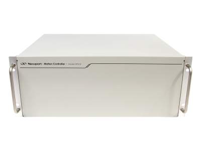 XPS-D |
 XPS-RLD |
|---|---|
|
|
Optics
Flex-PCB lasers typically operate at 355 nm (UV) and possibly 532 nm (green). We recommend using laser line optics when possible because they’re optimized for a specific wavelength and will perform better than a broadband optic.
Criteria for Selecting Optics
- Wavelength
- Laser Induced Damage Threshold (LIDT)
- Substrate Material
- Coating
- Reflectivity/Transmission
- Size and Shape
High-Energy Laser Mirrors
High-energy laser mirrors optimized for 355 and 532 nm offer very high reflectivity and damage thresholds, and standard broadband metallic mirrors offer a more economic option for good performance and value over very broad spectral ranges.
| High-Energy Laser Mirrors | ||
|---|---|---|
| Wavelength | 355 nm | 532 nm |
| CW Damage Threshold | 3 kW/cm2 | |
| Pulsed Damage Threshold | 3.5 J/cm2 @ 10 ns, 20 Hz | 10 J/cm2 @ 20 ns, 20 Hz |
| Reflectivity | Rs > 99.7% Rp > 99% |
|
| Diameter | 1 and 2 inch | |
| Substrate Material | UV Grade Fused Silica | |
| Angle of Incidence | 45° | |
High-Energy Plano-Convex Lenses
High-energy lenses optimized for 355 and 532 nm offer very high transmission and damage thresholds, and standard fused silica lenses offer good performance and value over very broad spectral ranges.
| High-Energy Spherical Lenses | ||
|---|---|---|
| Wavelength | 355 nm | 532 nm |
| Pulsed Damage Threshold | 15 J/cm2 @ 20 ns, 10 Hz | |
| Average Reflectivity per Surface | < 0.25% | |
| Diameter | 1 inch | |
| Substrate Material | High Purity Fused Silica | |
Nanotexture Surface Lenses
Highest laser damage resistance and lowest reflection loss
| Nanostructure Surface Fused Silica Plano-Convex Lenses | |
|---|---|
| Wavelength | 250 to 550 nm |
| CW Damage Threshold | 15 MW/cm2 |
| Pulsed Damage Threshold | 35 J/cm2 @ 10 ns, 1064 nm |
| Reflection Loss | 0.1% |
| Diameter | 0.5 in. |
| Shapes | Plano-Convex or Plano-Concave |
| Substrate Material | High Purity Fused Silica |
| Other Features | Sub-λ AR nanotextures etched directly into surface (no thin film coatings) |
CO2 Laser Lenses
If you happen to be using CO2 lasers in your FPC processing operation, we offer low absorption lenses that are specially designed to be used with high powered 10.6 micron CO2 lasers of up to several kilowatts.
In particular, our Black Magic series features low absorption rates of less than 0.15% of laser power, and our Clear Magic series features ultra-low absorption rates of less than 0.13%, and consequently, higher transmission of the laser energy through the lens. This leads to higher efficiency, superior performance and longer lifetimes for your system.
These zinc selenide lenses are CNC manufactured for the highest accuracy, uniformity and consistency. Plano-convex and mensicus lenses with diameters from just over 1 inch to 2 inches and various focal lengths are available. And if you think a standard AR coating will be sufficient for your application, the Duralens series uses the same substrates but with a standard 10.6-micron coating.
| CO2 Laser Lenses | |||
|---|---|---|---|
| Coating | Duralens™ | Black Magic™ | Clear Magic™ |
| Wavelength | 10.6 µm | ||
| Transmission | >99.3% | >99.35% | >99.37% |
| Absorption | <0.2% | <0.15% | <0.13% |
| Reflection | <0.2% | <0.25% | <0.25% |
| Diameters | 1.1 to 2.5 in. | 1.1 to 2.5 in. | 1.1 to 2.0 in. |
| Shapes | Plano-Convex Meniscus |
||
| Substrate Material | ZnSe | ||
| Other Features | Compatible with CO2 lasers in the kW range | ||
High-Energy Polarizing Cube Beamsplitters
Optimized for 355, 532 and 1064 nm, these cubes offer high damage thresholds, efficient polarization, and high extinction ratio.
| High-Energy UV Polarizing Cube Beamsplitters | Laser Line Polarizing Cube Beamsplitters | |
|---|---|---|
| Wavelength | 355 nm | 532 nm |
| Pulsed Damage Threshold | 5 J/cm2 | 10 J/cm2 |
| Reflectivity | Rs > 99% | Rs > 99.5% |
| Transmission | Tp > 90% | Tp > 95% |
| Extinction Ratio | Tp/Ts >200:1 | |
| Size | 1 in. | 0.5 in. |
| Substrate Material | UV Grade Fused Silica | |
|
Other Features |
Optically contacted, no cement |
|
Zero-Order Waveplates (λ/4 and λ/2)
Very high damage threshold, low sensitivity to temperature and wavelength variation.
| Zero-Order Waveplates | ||
|---|---|---|
| Wavelength | 355 nm | 532 nm |
| CW Damage Threshold | 2 MW/cm2 | |
| Reflectivity per Surface | < 0.25% | |
| Diameter | 0.5 and 1 in. | |
| Substrate Material | Quartz | |
| Temperature Coefficient | 0.0001 λ/°C | |
| Other Features | ±λ/300 retardation accuracy | |
Opto-Mechanics
There are many criteria to consider when selecting components, but here are the ones we think are important to start off with when you’re trying to narrow down the hundreds of choices out there for optical mounts.
First, resolution or sensitivity. How fine will the adjustments be that you’ll be making? Each mount’s resolution is determined by the threads-per-inch, or TPI, of its adjustment screws. MKS offers mounts with 50 all the way to 254 TPI. We also have a variety of drive types from high precision adjustment screws to differential micrometers.
Next, and probably the most important in the long term, is stability. Once you have your position set, you don’t want it to move. An unstable system could lead to potential downtime due to misalignment and other potential errors. One source of instability is thermal drift, which can be a real problem because a high powered laser can potentially heat up the area that that these optics are in, then heat up the object itself, which will lead to heating up the mount as well. One way to deal with thermal drift is to choose appropriate materials, and we’ve found that stainless steel mounts produce the least amount of thermal drift and shift. Other sources of instability are vibration and shock, so some mounts’ mechanical designs deal with vibration and shock better than others do.
Criteria for Selecting Optical Mounts
- Resolution/Sensitivity
- Long Term Stability
- Lockable
- Size and Shape
Optical component mounts are needed to hold and adjust optics. Long term stability and low drift is crucial. Minimizing drift caused by vibrations or thermal drift over time will ensure laser alignment to the desired spot and also reduce any potential downtime due to misalignment and errors. Having a locking mechanism on these mounts can also prevent misalignment of the beam, especially during shipping and also if anything else happens during usage.
HVM industrial mounts are recommended for robust long term usage in compact space. The Suprema® mirror mount is excellent for its stainless steel construction that gives better thermal performance than an aluminum mirror mount. Ultra-fine 254-TPI adjusters provide alignment sensitivity as low as 1.5 arc sec. For applications that are really concerned about the thermal changes that can be potentially caused by prolonged high powered laser usage, the ZeroDrift™ version will compensate for some thermal changes as well. For those mirror mounts that need to be set-and-forget for a long period of time, we recommend the MFM flexure mirror Mount. These are excellent for their small footprint so that machine size can be reduced.
- Suprema® Stainless Steel Mirror Mounts: the industry's best thermal performance for long-term stability.
- Suprema™ ZeroDrift™ Mirror Mounts: 85% improved optical pointing stability through thermal drift compensation.
 Suprema |
Suprema® ZeroDrift™ |
|
|---|---|---|
| Optic Diameters | 0.5, 1 and 2 in. | 0.5 and 1 in. |
| Resolution | 50, 100, 127 and 254 TPI | 100 TPI |
| Angular Range | ±7° | ±4° |
| Material | Stainless Steel |
Stainless Steel |
| Drive Types | Knob Hex Key Exchangeable Actuators |
Knob Hex Key |
| Lockable Versions | Yes | Yes |
| Other Versions | Clear-Edge Front- and Rear-Loading Right- and Left-Handed Low Wavefront Distortion ZeroDrift™ |
Thermal drift compensation Front- and Rear-Loading |
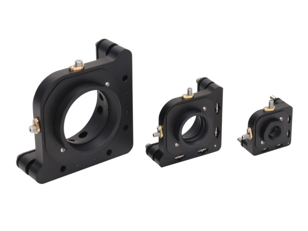
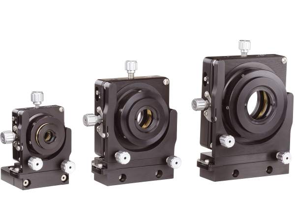
- HVM Top-Adjust Mirror Mounts: for use in compact spaces so your hands do not have to cross the beam path for adjustment.
- MFM Flexure Mirror Mounts: designed for "set and forget" applications.
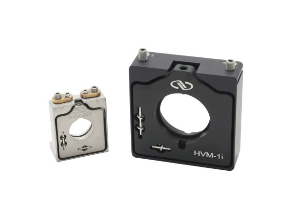 HVM-Series |
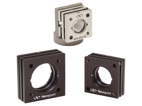 MFM-Series |
|
|---|---|---|
| Optic Diameters | 0.5, 1 and 2 in. | 0.5, 0.75 and 1 in. |
| Resolution | 80 and 100 TPI | 80 and 100 TPI |
| Angular Range | ±2.5°, ±3° and ±3.5° | ±2.5° |
| Material | Anodized Aluminum, Stainless Steel | Stainless Steel |
| Drive Types | Hex Key | Hex Key |
| Lockable Versions | Yes | No |
| Other Features | Front- and Rear-Loading Versions | Shock Resistant Front- and Rear-Loading Versions Adhesive wells for permanent mounting |
- A-Line™ Fixed Position Lens Mounts: fast, easy and economic mounting, aligning and focusing of optics.
- Compact Lens Positioners: ideal solution for applications with limited table space.
- LP Precision Multi-Axis Lens Positioners: highest performing lens positioners.
 A-Line |
 Compact |
 LP-Series |
|
|---|---|---|---|
| Optic Diameters | 0.5 to 3 in. | 0.5, 1 and 2 in. | 0.5, 1 and 2 in. |
| Resolution | - | 100 TPI | 100 TPI |
| Adjustments | Fixed | XY, XYZ, XYZθxθy | XY, XYZ, XYZθxθy |
| Material | Aluminum | Aluminum | Aluminum |
| Other Features | Self-aligning design Large clear aperture Compatible with A-Line alignment system |
Adapters for other optics Lockable positions |
Zero-freeplay XY mechanism True Gimbal adjustments Independent non-influencing locks Adapters for other optics |
- Ultima® Gimbaled Cube/Prism Mount: precision alignment of beamsplitter cubes and prisms.
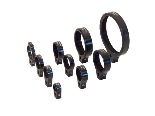
- RSP High Performance Optic Rotation Mounts: smooth, continuous 360° rotation of optics.
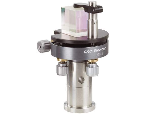 UGP-1 |
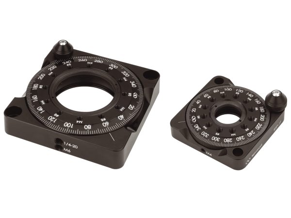 RSP-Series |
|
|---|---|---|
| Optic Size | 0.5 and 1 in. cube | 1 and 2 in. |
| Resolution | 100 TPI | 4 arc min |
| Angular Range | ±5° | 360° |
| Material | Aluminum | Aluminum |
| Drive Types | Knob w/ Hex Hole | Coarse: knurled edge Fine: knob |
| Lockable | Yes | Yes |
| Other Features | True gimbal motion Adapters for other optics |
Full ball bearing races Adapters for other optics |
Vibration Isolation
NewDamp™ Elastomeric Vibration Isolators
Supports and dampens high acceleration amplitudes
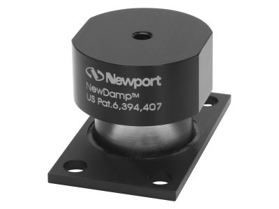
| NewDamp™ Elastomeric Isolators | |
|---|---|
| Minimum Loads | 6-45 kg |
| Load Capacity | 8 to 200 kg (per isolator) |
| Loss Factor | 0.5 to 0.8 in 10-100 Hz range |
| Height | 1.32 to 3.28 in. |
| Base Size | 2.4 x 2.4 to 4.5 x 4.5 in. |
| Other Features | Constant natural frequency design Fast settling times Cleanroom compatible Breadboard, Microlock and X95 compatible |
Resources
Cutting and Drilling of PCB Materials Using UV Talon® Laser(315.1 kB, PDF) Processing Flexible Printed Circuit and Microelectronics Materials with UV ns Lasers(438.2 kB, PDF) UV Lasers for Fast Flex-PCB Processing(1.1 MB, PDF) New Materials in 5G Flex Circuits Process with Picosecond UV Lasers(1.1 MB, PDF) High Quality Flex Printed Circuit (FPC) Processing with UV ps Lasers(474.8 kB, PDF)