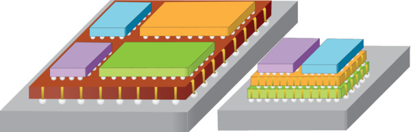
System-in-Package (SiP) Manufacturing
To help maintain the pace of growth in the number of transistors on a chip, new innovations in semiconductor manufacturing are needed. One area of innovation focuses on how chips are packaged. As traditional chip-level scaling is reaching its limits, an alternative is system-level scaling through system-in-package (SiP). Also known as 2.5D/3D packaging, SiP enables heterogenous integration, which is the packing of individual semiconductor chips with various functions such as memory and logic onto a single substrate to achieve system-level performance. Thus, SiP has the potential to continue and possibly exceed the growth trajectories for the number of transistors on a chip. In order to improve and advance SiP packaging, lasers are required to perform processes that traditional methods cannot, especially when working with materials such as ceramics, organics and even glass.
SiP Manufacturing Challenges
As SiP packages contain two or more chips stacked vertically as well as horizontally, micro-vias with typical diameters ranging from approximately 200 to just a few microns are used to provide vertical electrical connections among them. These micro-vias may be present either in an interposer (which is also referred to as an IC substrate) layer or within the chips themselves. Formation of micro-vias is commonly accomplished through chemical etching, but this process has limitations. Although chemical etching is a proven methodology for silicon and glass, etching cannot be used with ceramics or organic materials. Additionally, the waste management required for chemical etching processes presents extra complications and costs.
Cutting various materials as part of the SiP manufacturing process is also a very delicate process. Whether cutting an interposer, depaneling a package substrate or scribing and dicing a silicon die, the size of the cuts can be extremely small and must be made with the highest precision and minimal surrounding damage. As chip designs become even more advanced and miniaturized with higher densities, the type of cuts required will also become more complex.
Furthermore, as the materials become thinner, contact-based mechanical methods could cause damage such as cracks and tears, so therefore, a non-contact laser process will improve yields and throughput.
The assorted types of materials which SiP packages comprise—for example, ceramics, organic laminate and glass—respond differently to different manufacturing processes. To further complicate matters, some materials are inhomogeneous, such as ABF and FR4, which contains glass fibers and epoxy resin, and some laminates, which are embedded with copper traces. Traditional manufacturing processes including mechanical saws and etching may work well with some materials but not as well with others. The same is also true with laser manufacturing processes, as not all lasers are the same. Furthermore, tradeoffs in areas including speed, precision, surrounding damage and cost are always present when comparing manufacturing processes.
MKS Solutions for System-in-Package Manufacturing
MKS has a deep understanding of the challenges faced in designing and building SiP manufacturing systems. We’ve turned this knowledge into unique product features that provide an advantage when used in SiP manufacturing.
| Challenges in SiP Manufacturing | MKS Solutions |
|---|---|
| Maximizing throughput & yield | Pulsed lasers for high speed, yield and precision micromachining Fast, high power laser measurement and profiling High power/high fluence optics to manage the lasers High speed and precision motorized positioners |
| Improving SiP quality and reliability | Nanosecond and picosecond lasers for highest quality micromachining Robust, stable optical mounts |
| Scaling the manufacturing process | Applications engineering expertise & full range of products |
Your Partner for SiP Manufacturing
- 50+ years and thousands of alignment systems for optical applications
- Long-term partner to semiconductor manufacturing companies
- Full range of products: lasers, optics, motion, opto-mechanics, beam analysis
- Custom capabilities
- Product availability
- Ability to scale with you
- Global corporation and presence
 Lasers |
 Beam Analysis |
 Motion Control |
 Opto-Mechanics |
|---|---|---|---|
|
|
|
|
Lasers
Ultrashort Pulse Lasers
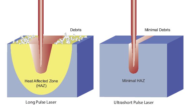
One of the challenges for laser materials processing—including cutting and drilling—is removing only the desired material, usually through localized heating, while at the same time minimizing the extent of the heat-affected zone (HAZ) to any of the remaining material. Delivering laser irradiation with near perfect beam quality precisely to the target region is a necessary step to achieving this desired result. Shorter wavelengths and, in particular, shorter pulse widths are advantageous to achieving higher-quality results.
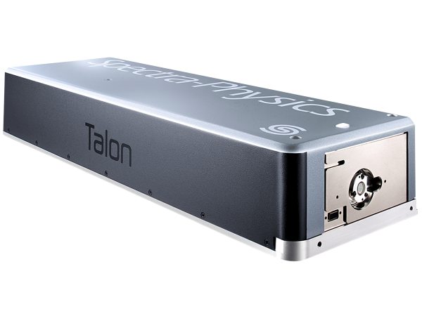
For singulation of SiP devices, lasers in the ns pulse width regime at UV and green wavelengths, such as the Spectra Physics® Talon laser, may be suitable. However, challenges arise if excess heating cannot be tolerated, especially as these devices become further condensed and more densely packed. This leads to an interest in laser processing with even shorter pulse durations for reduced HAZ. Such may be the case if there are encapsulations that use a heat-sensitive bonding media, such as solder or adhesive, which may fail under excess thermal loading. Moreover, the presence of copper traces embedded within the SiP laminate, which can become excessively hot and result in the potential for layer delamination, can create additional difficulties.
To meet these challenges and to enable the advancement of SiP technology, ultrashort pulse (USP) lasers, like the Spectra Physics IceFyre® laser, can be employed. Ultrashort pulse widths in the ps and fs regime yield intense peak powers that result in nonlinear absorption at the sample for instantaneous material vaporization, very minimal heat transfer into the material, and a negligible HAZ. The result is a fast, high precision, high-quality cut or drill which leads to higher throughput and fewer part failures.
Picosecond Lasers
- IceFyre® Picosecond Lasers: Spectra-Physics IceFyre picosecond lasers set a new standard for picosecond micromachining and can provide the ultimate solutions for SiP manufacturing. The UV version enables premium quality drilling of micro-vias through ceramic, organic and glass interposers. Both the UV and green versions are great for cutting ceramic interposers, depaneling and scribing and dicing silicon dies. Additionally, the IR version can be used to cut glass interposers. Based on Spectra-Physics’ It’s in the Box™ design, the laser and controller are integrated into a single, compact package, and IceFyre is manufactured to provide 24/7 industrial reliability.
| IceFyre® | ||||
|---|---|---|---|---|
| Wavelengths | UV | Green | IR | 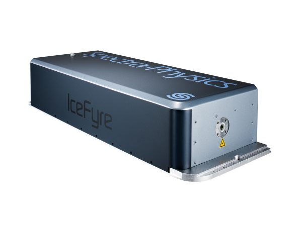 |
| Power | Up to >50 W | |||
| Pulse Width | <12 ps | <15 ps | ||
| Repetition Rates | Single Shot to 10 MHz | |||
| Max Pulse Energy | Up to >40 µJ | Up to >60 µJ | Up to >200 µJ | |
| Other Features | 24/7 industrial reliability TimeShift™ technology for pulse control Laser/controller in single, compact package |
|||
Nanosecond Lasers
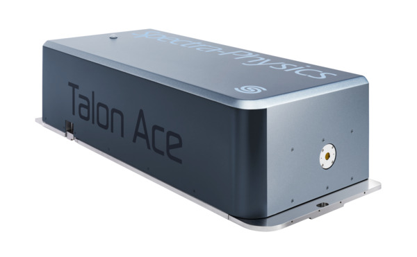
- Talon® Ace™ Lasers: Delivering an industry-leading >100 Watts of UV power, Talon Ace offers the lowest cost-per-Watt and cost of ownership for high power nanosecond UV lasers. This laser can be employed for a whole host of applications including drilling micro-vias through ceramic, organic laminate and glass interposers, cutting ceramic and organic laminate interposers, depaneling, and scribing and dicing dies. Talon Ace also includes our proprietary TimeShift programmable burst-mode technology for the most versatile pulse control, leading to increased process speed and quality. Designed to provide 24/7 industrial reliability, the laser and controller are integrated into a single, compact package.
- Talon® Nanosecond Lasers: For the best combination of performance, reliability and cost in SiP laser manufacturing, Spectra-Physics Talon lasers deliver excellent results. Talon works exceptionally well for cutting ceramic and organic laminate interposers, depaneling and scribing and dicing silicon dies. The UV version in particular is also able to drill micro-vias through ceramic and organic interposers. The Talon provides high quality results, but its cuts and drills may not be as pristine as the IceFyre’s. Talon’s advantage over IceFyre, though, is that it can cut and drill faster. Based on Spectra-Physics’ It’s in the Box™ design, the laser and controller are integrated into a single, compact package, and Talon is manufactured to provide 24/7 industrial reliability.
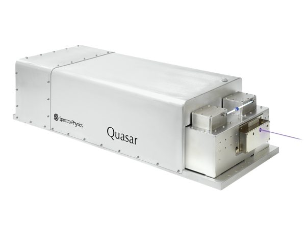
- Quasar® High-Power Nanosecond Lasers: Other lasers highly suited for SiP manufacturing are the Spectra-Physics Quasar® and Talon® Ace nanosecond series of lasers. The Talon Ace UV100 is the highest-powered single mode UV laser in the industry, so it delivers fast micromachining and provides 24/7 industrial reliability. Like the IceFyre and Talon, the UV and green versions of the Quasar and Talon Ace can also be used for depaneling, scribing and dicing dies. And like the UV version of the IceFyre, the Quasar UV and Talon Ace UV can also drill micro-vias through ceramic, organic and glass interposers.
 Talon Ace |
 Talon |
 Quasar |
|
|---|---|---|---|
| Wavelengths | UV | UV or Green | UV or Green |
| Power |
>100 W |
UV: Up to >45 W Green: Up to >40 W |
UV: Up to >80 W Green: Up to >95 W |
| Pulse Width |
<2 to >50 ns |
UV: <25 or 40 ns Green: <25 ns |
<2 to >100 ns |
| Repetition Rates |
Single shot to 5 MHz |
0 to 500 kHz | 0 to 3.5 MHz |
| Max Pulse Energy |
Up to >500 µJ |
UV: Up to >500 µJ Green: Up to 1000 µJ |
UV: Up to >400 µJ Green: Up to >475 µJ |
| Other Features |
24/7 industrial reliability TimeShift technology for pulse control Laser/controller in single, compact package |
Laser/controller in single, compact package 24/7 industrial reliability E-Pulse™ technology for superb stability |
24/7 industrial reliability TimeShift™ technology for pulse control |
System-in-Package Laser Selection Guide
Presented here is a summary of recommended MKS lasers for various SiP manufacturing applications. Please use this as a reference guide only, and always contact us to discuss your application and requirements in detail so that we may provide the best solution for you.
| Talon® Ace™ | IceFyre® | Talon® | Quasar® | |||||
|---|---|---|---|---|---|---|---|---|
| UV | UV | Green | IR | UV | Green | UV | Green | |
|
Drilling Ceramic Micro-vias |
✓ | ✓ | ✓ | ✓ | ||||
| Drilling Organic Laminate Micro-vias | ✓ | ✓ | ✓ | ✓ | ||||
| Drilling Glass Micro-vias | ✓ | ✓ | ✓ | |||||
| Cutting Ceramic Interposer | ✓ | ✓ | ✓ | ✓ | ✓ | ✓ | ||
| Cutting Organic Laminate Interposer | ✓ | ✓ | ✓ | ✓ | ||||
| Cutting Glass Interposer | ✓ | |||||||
|
Cutting SiP Package Substrate (Depaneling) |
✓ | ✓ | ✓ | ✓ | ✓ | ✓ | ||
|
Scribing/Dicing* Silicon Die |
✓ | ✓ | ✓ | ✓ | ✓ | ✓ | ✓ | |
* Dicing thin wafers < 100 µm
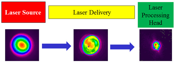
Laser Beam Analysis
Even with the advantages that lasers have over traditional tools, laser systems can still degrade over time. Some causes of degradation include thermal effects on a laser system’s internal components, vibrations or shock and debris near the processing site. These issues could affect laser performance in a number of ways. First, output power may be reduced, causing the laser to be less efficient. Another problem that may be caused is a change in the focus or other profile of the beam, which may lead to a cut or drill to be off target, too deep, low quality or possibly damaging to another part of the material.
Therefore, to ensure the highest quality of manufacturing SiP chips and to minimize the possibility of production down-time, it is crucial to monitor the laser beam frequently with appropriate instruments–like Ophir® power sensors, power meters and beam profilers–that can operate at the laser’s wavelength while handling its maximum output power level.
Causes of Laser System Degradation
- Thermal Effects
- Debris from Process
- Vibrations and Shock
Criteria for Beam Analysis Instruments
There are three types of beam analysis instruments to monitor your laser: (1) sensors and detectors to measure power, (2) power meters to process the information provided by sensors and (3) beam profilers to determine focus position and other beam characteristics. Shown below are the main criteria for choosing such instruments.
Laser Sensors- Compatible with laser wavelength
- Power/energy range/density
- Beam size
- Calibrated power measurement
- Compatible with sensor
- Connect to system/PC
- Track process data over time
- Compare multiple measurements at once
- Measurement of multiple attributes
- Focal shift
- Focal spot size
- Laser power and power density
- Changes over time
- Laser propagation characteristics
- Speed of measurement
Laser Power Sensors
MKS offers a comprehensive portfolio of Ophir® laser thermal power sensors, several of which can measure the optical output power of short- and ultrashort-pulsed lasers such as IceFyre, Talon, Talon Ace and Quasar. These sensors have a very high damage threshold to withstand the high optical peak power delivered by each pulse. Ophir sensors and meters meet the ISO/IEC 17025 standard for calibrated devices.
- Laser Thermal Power Thermal Sensors: very high damage thresholds for hundreds of watts power measurement.
| F150(200)A-CM-16 | 30(150)A-SV-17 | F80(120)A-CM-17 | ||
|---|---|---|---|---|
| Spectral Range | 0.248-9.4 µm | 0.19-11 µm | 0.248-9.4 µm | 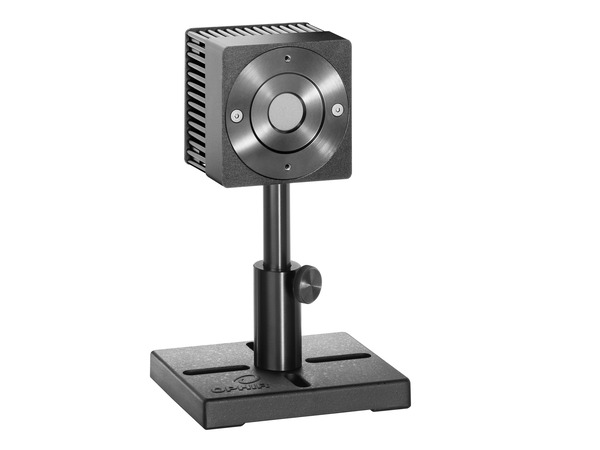 |
| Power Range | 300 mW - 200 W | 100 mW - 150 W | 100 mW - 120 W | |
| Energy Range | 50 mJ – 200 J | 50 mJ – 300 J | 50 mJ – 200 J | |
| Max Avg Power Density | 35 kW/cm2 | 60 kW/cm2 | 35 kW/cm2 | |
| Max Energy Density (2 msec) | 45 J/cm2 | 50 J/cm2 | 45 J/cm2 | |
| Aperture | Ø16 mm | Ø17 mm | Ø17.5 mm | |
| Response Time | 3 sec | 1.7 sec | 2 sec | |
| Other Features | Not water-cooled | |||
The recommended products above are the most popular models for semiconductor manufacturing. We have a lot more than these and you can use our online tools to find the ones that best fit your requirements.
Power Meters
Ophir laser power and energy meters work on the smart plug principle. This means that almost any power meter can work – plug and play – with almost any of the wide range of Ophir optical sensors.
| Power Meters | Virtual Power Meters | ||
|---|---|---|---|
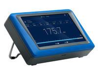 Centauri |
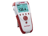 StarBright Handheld |
 Juno+ |
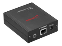 EA-1 |
|
|
|
|
Beam Profilers
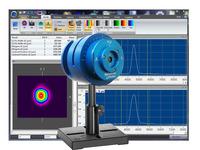
An effective way to analyze beam profile is with a camerabased system. Ophir beam profiling cameras allow real-time viewing and measuring of a laser’s structure in high resolution. Camera-based systems can also measure cross-sectional intensity of the laser and provide a complete 2-dimensional view of the laser mode.
- SP932U Beam Profiling Camera: high resolution, real-time viewing and measuring of laser structure with highest accuracy in the industry
- Pyrocam™ IV Beam Profiling Camera: generates full 2D profiles of CO2 and NIR lasers in CW or pulsed modes of any frequency
- NanoScan™ 2s Pyro/9/5 Scanning-Slit Profiler: sub-micron precision for generating 2 orthogonal linear profiles of a CO2 or IR beam
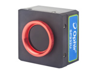 SP932U |
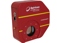 Pyrocam™ IV |
 NanoScan™ |
|
|---|---|---|---|
| Spectral Range | 190-1100 nm | 13-355 nm, 1.06-3000 µm | 190 nm-100 µm |
| Power Range | 5 mW to 100 W | ||
| Damage Threshold | 50 W/cm2, 1 J/cm2, <100 ns pulse width | 2 W over entire array, 20 mJ/cm2 (1 ns pulse) | |
| Beam Sizes | 34.5 µm to 5.3 mm | 1600 µm to 25.4 mm | 20 µm to 6 mm |
| Pixels | 2048 x 1536 Effective Pixels, 3.45 µm Pixel Size | 320 x 320 Effective Pixels, 75 µm Pixel Size | |
| PC Interface | USB 2.0 | GigE | USB 2.0 |
| Other Features | BeamGage® software included UltraCal™ correction algorithm Measures cross-sectional intensity 72 dB true dynamic resolution 24 Hz frame rate in 12-bit mode |
BeamGage® software included CW or pulsed beams Measures cross-sectional intensity |
Graphical user interface software included CW or >25 kHz pulsed beams |
Motion Control
Guaranteed Motion Control Performance
- Stages that MKS ships meet or exceed the guaranteed specifications
- Metrology reports included with each stage (ASME B5.57 and ISO 230-2 standards)
- Typically, the product will perform ~2x better than the guarantee
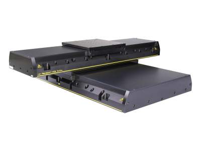
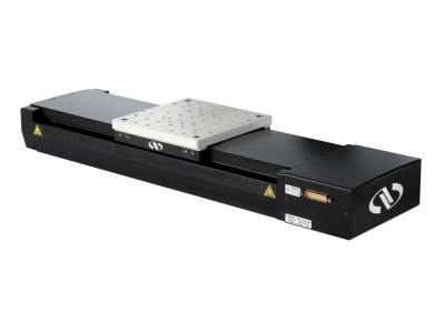
IDL-LM Series Industrial Linear Motor Stages
The target for a laser materials process—for instance, a silicon wafer for scribing and dicing—will often have to be positioned for the laser to perform its operation. The positioning requirements for SiP manufacturing can be extremely challenging. Accuracy in two dimensions is typically on the order of microns, as is the repeatability to ensure consistent results. To meet throughput demands, the required speed can be up to 1 meter/sec.
These performance requirements must be achievable in a demanding production environment. Thus, only high performing motorized positioners designed for continuous usage in industrial environments, like the IDL series linear positioners, should be considered.
| IDL-LM Series | |
|---|---|
| Travel Range | 100 to 1200 mm |
| Speed | 2000 mm/s |
| Load Capacity | 450 to 2,000 N |
| Accuracy | ±2 to ±5 µm |
| Repeatability | ±0.25 to ±0.5 µm |
| Pitch | ±15 to ±65 µrad |
| Yaw | ±15 to ±40 µrad |
| Other Features | Ironless Linear Motor Recirculating ball bearings Industrial grade hard covers |
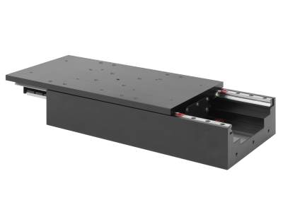
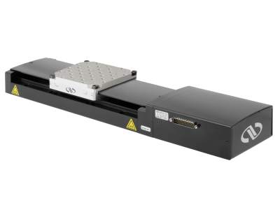
XM-S Series Linear Motor Stages
High sensitivity and outstanding trajectory accuracy in a compact, robust and cost-effective package.
| XM-S Series | |
|---|---|
| Travel Range | 50 to 350 mm |
| Minimum Incremental Motion | 1 nm |
| Speed | 300 mm/s |
| Load Capacity | 100 to 300 N |
| Accuracy | ±0.2 to ±0.5 µm |
| Repeatability | ±0.03 to ±0.035 µm |
| Straightness & Flatness | ±0.37 to ±0.75 µrad |
| Other Features | Ironless Linear Motor Crossed-roller bearings |
IMS Series Long-Travel Aluminum Linear Positioners
High load capacity, long travel, fast movement capable of high-duty cycles in industrial applications
| Stepper Motor | DC Motor | |
|---|---|---|
| Travel Range | 300 to 600 mm | |
| Speed | 100 m/sec | 200 mm/sec |
| Load Capacity | 600 N | |
| Pitch | ±37 to ±50 µrad | |
| Yaw | ±15 to ±30 µrad | |
| Accuracy | ±2.5 to ±4 µm | |
| Other Features | Double-row recirculating ball bearings Linear motor version available |
|
ILS Series Mid-Travel Aluminum Linear Positioners
High load capacity, mid-travel, fast movement capable of high-duty cycles in light industrial applications
| Stepper Motor | DC Motor | |
|---|---|---|
| Travel Range | 50 to 250 mm | |
| Speed | 50 m/sec | 100 mm/sec |
| Load Capacity | 250 N | |
| Pitch | ±15 to ±42 µrad | |
| Yaw | ±12 to ±25 µrad | |
| Accuracy | ±0.6 to ±1.7 µm | |
| Other Features | Double-row recirculating ball bearings Linear motor version available |
|
Motion Controllers
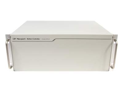 XPS-D |
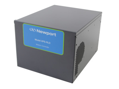 XPS-RLD |
|---|---|
|
|
Optics
For the SiP manufacturing lasers required, you will likely be operating at 355, 532 and 1064 nm. There are broadband and laser line optics available, but since you’ll know specifically which wavelength you’ll have, we recommend using laser line optics when possible because they’re optimized for a specific wavelength and will perform better than a broadband optic.
Dozens of Newport standard catalog optics are designed to operate with high-energy lasers such as those used in SiP laser manufacturing. Mirrors, lenses, beam splitter cubes and waveplates are readily available in various sizes and shapes whose substrate materials and coatings are optimized for the 355, 532 and 1064 nm wavelengths. These high-performing optics can withstand laser fluences in the Joules and sometimes tens of Joules of pulsed energy per square centimeter to enable many solutions for SiP processing.
Criteria for Selecting Optics
- Wavelength
- Laser Damage Threshold
- Substrate Material
- Coating
- Reflectivity/Transmission
- Size and Shape
High-Energy Laser Mirrors
High-energy laser mirrors optimized for 355, 532 and 1064 nm offer very high reflectivity and damage thresholds, and standard broadband metallic mirrors offer a more economic option for good performance and value over very broad spectral ranges.
| High-Energy Laser Mirrors | |||
|---|---|---|---|
| Wavelength | 355 nm | 532 nm | 1064 nm |
| CW Damage Threshold | 3 kW/cm2 | ||
| Pulsed Damage Threshold | 3.5 J/cm2 @ 10 ns, 20 Hz | 10 J/cm2 @ 20 ns, 20 Hz | 45 J/cm2 @ 10 ns, 20 Hz |
| Reflectivity | Rs > 99.7% Rp > 99% |
||
| Diameter | 1 and 2 inch | ||
| Substrate Material | UV Grade Fused Silica | ||
| Angle of Incidence | 45° | ||
High-Energy Plano-Convex Lenses
High-energy lenses optimized for 355, 532 and 1064 nm offer very high transmission and damage thresholds, and standard fused silica lenses offer good performance and value over very broad spectral ranges.
| High-Energy Spherical Lenses | |||
|---|---|---|---|
| Wavelength | 355 nm | 532 nm | 1064 nm |
| Pulsed Damage Threshold | 15 J/cm2 @ 20 ns, 10 Hz | ||
| Average Reflectivity per Surface | < 0.25% | ||
| Diameter | 1 inch | ||
| Substrate Material | High Purity Fused Silica | ||
Nanotexture Surface Lenses
Highest laser damage resistance and lowest reflection loss
| Nanostructure Surface Fused Silica Plano-Convex Lenses | |
|---|---|
| Wavelength | 250 to 550 nm or 500 to 1100 nm |
| CW Damage Threshold | 15 MW/cm2 |
| Pulsed Damage Threshold | 35 J/cm2 @ 10 ns, 1064 nm |
| Reflection Loss | 0.1% |
| Diameter | 0.5 in. |
| Shapes | Plano-Convex or Plano-Concave |
| Substrate Material | High Purity Fused Silica |
| Other Features | Sub-λ AR nanotextures etched directly into surface (no thin film coatings) |
CO2 Laser Lenses
For SiP operations that utilize CO2 lasers, Ophir lowabsorption CO2 laser lenses are specially designed to be used with high-powered 10.6-micron CO2 lasers of up to several kilowatts. These lenses absorb up to 50% less CO2 laser energy than standard anti-reflection coatings, resulting in higher efficiency, superior performance and longer lifetime.
| CO2 Laser Lenses | |||
|---|---|---|---|
| Coating | Duralens™ | Black Magic™ | Clear Magic™ |
| Wavelength | 10.6 µm | ||
| Transmission | >99.3% | >99.35% | >99.37% |
| Absorption | <0.2% | <0.15% | <0.13% |
| Reflection | <0.2% | <0.25% | <0.25% |
| Diameters | 1.1 to 2.5 in. | 1.1 to 2.5 in. | 1.1 to 2.0 in. |
| Shapes | Plano-Convex Meniscus |
||
| Substrate Material | ZnSe | ||
| Other Features | Compatible with CO2 lasers in the kW range | ||
High-Energy Polarizing Cube Beamsplitters
Optimized for 355, 532 and 1064 nm, these cubes offer high damage thresholds, efficient polarization, and high extinction ratio.
| High-Energy UV Polarizing Cube Beamsplitters | Laser Line Polarizing Cube Beamsplitters | ||
|---|---|---|---|
| Wavelength | 355 nm | 532 nm | 1064 nm |
| Pulsed Damage Threshold | 5 J/cm2 | 10 J/cm2 | |
| Reflectivity | Rs > 99% | Rs > 99.5% | |
| Transmission | Tp > 90% | Tp > 95% | |
| Extinction Ratio | Tp/Ts >200:1 | ||
| Size | 1 in. | 0.5 in. | |
| Substrate Material | UV Grade Fused Silica | ||
|
Other Features |
Optically contacted, no cement |
||
Zero-Order Waveplates (λ/4 and λ/2)
Very high damage threshold, low sensitivity to temperature and wavelength variation.
| Zero-Order Waveplates | |||
|---|---|---|---|
| Wavelength | 355 nm | 532 nm | 1064 nm |
| CW Damage Threshold | 2 MW/cm2 | ||
| Reflectivity per Surface | < 0.25% | ||
| Diameter | 0.5 and 1 in. | ||
| Substrate Material | Quartz | ||
| Temperature Coefficient | 0.0001 λ/°C | ||
| Other Features | ±λ/300 retardation accuracy | ||
Opto-Mechanics
Whenever optics are part of a laser system, they will have to be precisely positioned and steadily held over long periods of time. MKS offers the most comprehensive line of opto-mechanical components in the industry. Hundreds of optical mounts and positioners at various levels of performance and cost are readily available.
Criteria for Selecting Optical Mounts
- Resolution/Sensitivity
- Long Term Stability
- Lockable
- Size and Shape
Optical component mounts are needed to hold and adjust optics. Long term stability and low drift is crucial. Minimizing drift caused by vibrations or thermal drift over time will ensure laser alignment to the desired spot and also reduce any potential downtime due to misalignment and errors. Having a locking mechanism on these mounts can also prevent misalignment of the beam, especially during shipping and also if anything else happens during usage.
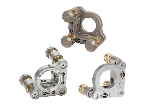
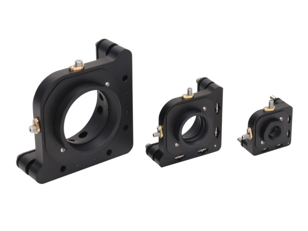
HVM industrial mounts are recommended for robust long term usage in compact space. The Suprema® mirror mount is excellent for its stainless steel construction that gives better thermal performance than an aluminum mirror mount. Ultra-fine 254-TPI adjusters provide alignment sensitivity as low as 1.5 arc sec. For applications that are really concerned about the thermal changes that can be potentially caused by prolonged high powered laser usage, the ZeroDrift™ version will compensate for some thermal changes as well. For those mirror mounts that need to be set-and-forget for a long period of time, we recommend the MFM flexure mirror Mount. These are excellent for their small footprint so that machine size can be reduced.
- Suprema® Stainless Steel Mirror Mounts: the industry's best thermal performance for long-term stability.
- M-Series Aluminum Mirror Mounts: the new standard for affordable mounts.
 Suprema |
 M-Series |
|
|---|---|---|
| Optic Diameters | 0.5, 1 and 2 in. | 0.5, 1 and 2 in. |
| Resolution | 50, 100, 127 and 254 TPI | 100 TPI |
| Angular Range | ±7° | ±4° |
| Material | Stainless Steel | Aluminum |
| Drive Types | Knob Hex Key Exchangeable Actuators |
Knob Hex Key |
| Lockable Versions | Yes | No |
| Other Versions | Clear-Edge Front- and Rear-Loading Right- and Left-Handed Low Wavefront Distortion ZeroDrift™ |
Clear-Edge Front- and Rear-Loading Right- and Left-Handed |
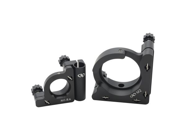
- HVM Top-Adjust Mirror Mounts: for use in compact spaces so your hands do not have to cross the beam path for adjustment.
- MFM Flexure Mirror Mounts: designed for "set and forget" applications.
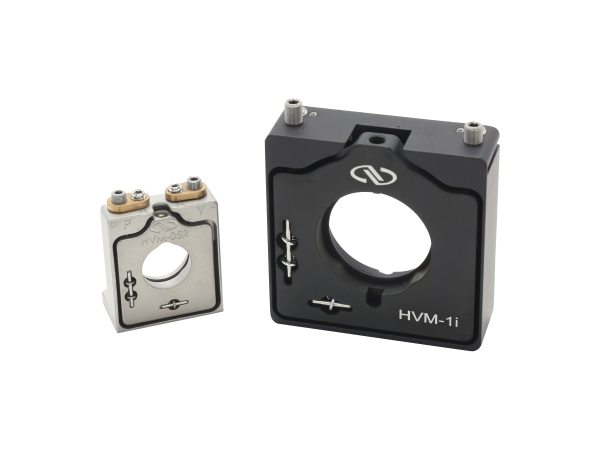 HVM-Series |
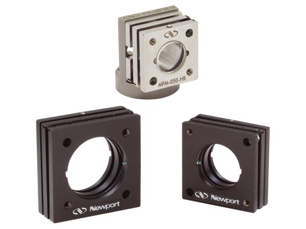 MFM-Series |
|
|---|---|---|
| Optic Diameters | 0.5, 1 and 2 in. | 0.5, 0.75 and 1 in. |
| Resolution | 80 and 100 TPI | 80 and 100 TPI |
| Angular Range | ±2.5°, ±3° and ±3.5° | ±2.5° |
| Material | Anodized Aluminum, Stainless Steel | Stainless Steel |
| Drive Types | Hex Key | Hex Key |
| Lockable Versions | Yes | No |
| Other Features | Front- and Rear-Loading Versions | Shock Resistant Front- and Rear-Loading Versions Adhesive wells for permanent mounting |
- A-Line™ Fixed Position Lens Mounts: fast, easy and economic mounting, aligning and focusing of optics.
- Compact Lens Positioners: ideal solution for applications with limited table space.
- LP Precision Multi-Axis Lens Positioners: highest performing lens positioners.
 A-Line |
 Compact |
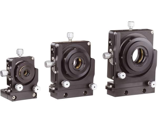 LP-Series |
|
|---|---|---|---|
| Optic Diameters | 0.5 to 3 in. | 0.5, 1 and 2 in. | 0.5, 1 and 2 in. |
| Resolution | - | 100 TPI | 100 TPI |
| Adjustments | Fixed | XY, XYZ, XYZθxθy | XY, XYZ, XYZθxθy |
| Material | Aluminum | Aluminum | Aluminum |
| Other Features | Self-aligning design Large clear aperture Compatible with A-Line alignment system |
Adapters for other optics Lockable positions |
Zero-freeplay XY mechanism True Gimbal adjustments Independent non-influencing locks Adapters for other optics |
- Ultima® Gimbaled Cube/Prism Mount: precision alignment of beamsplitter cubes and prisms.
- RSP High Performance Optic Rotation Mounts: smooth, continuous 360° rotation of optics.
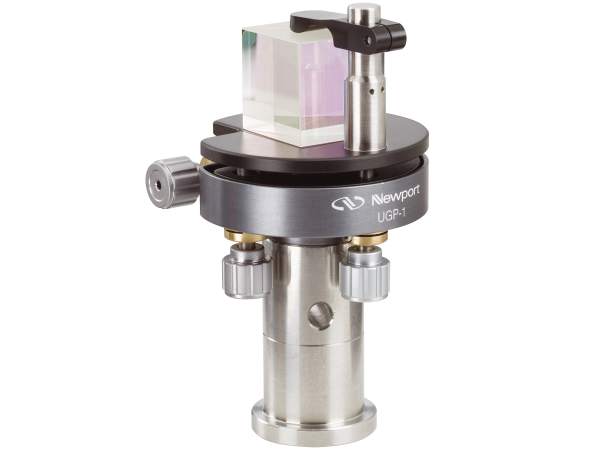 UGP-1 |
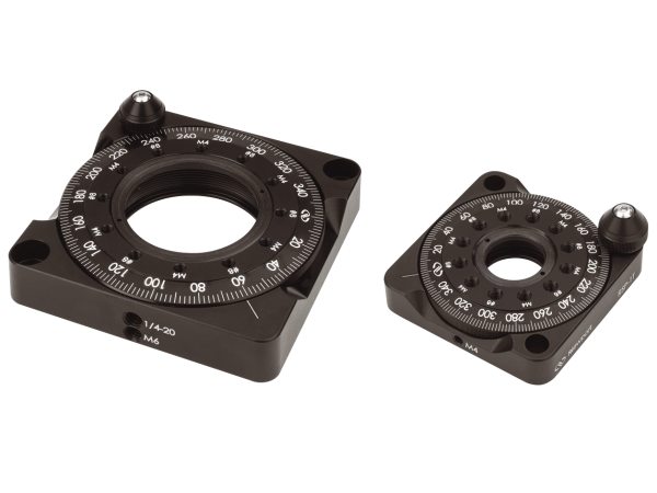 RSP-Series |
|
|---|---|---|
| Optic Size | 0.5 and 1 in. cube | 1 and 2 in. |
| Resolution | 100 TPI | 4 arc min |
| Angular Range | ±5° | 360° |
| Material | Aluminum | Aluminum |
| Drive Types | Knob w/ Hex Hole | Coarse: knurled edge Fine: knob |
| Lockable | Yes | Yes |
| Other Features | True gimbal motion Adapters for other optics |
Full ball bearing races Adapters for other optics |
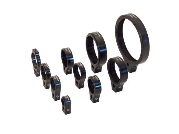
- PX Forkless Optical Pedestals: Long-term stability of a pedestal at 1/3 the space.
| PX Post | PX Pedestal | ||
|---|---|---|---|
| Diameter | 1 in. | 1 in. with 1.25 in. flange | 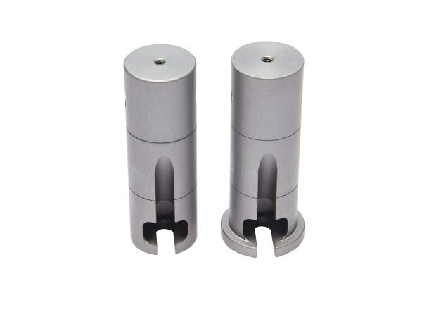 |
| Heights | 1, 2, 3 and 4 in. | ||
| Material | Stainless Steel | ||
| Other Features | Accessories for varying heights and mounting configurations | ||
Vibration Control
For applications that require holding alignments in place, we offer a comprehensive range of vibration isolation and damping solutions to ensure a stable system.
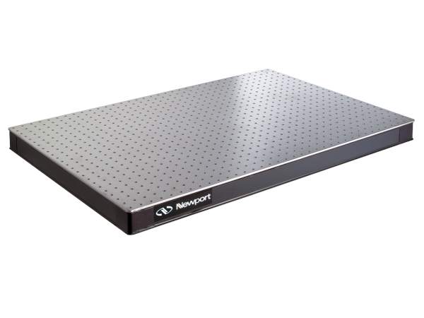 Breadboards |
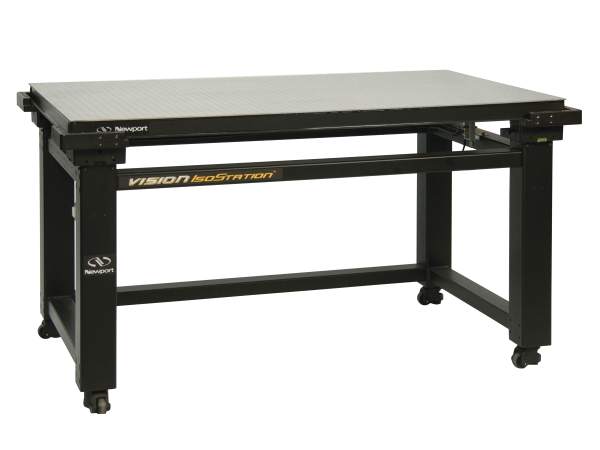 Workstations |
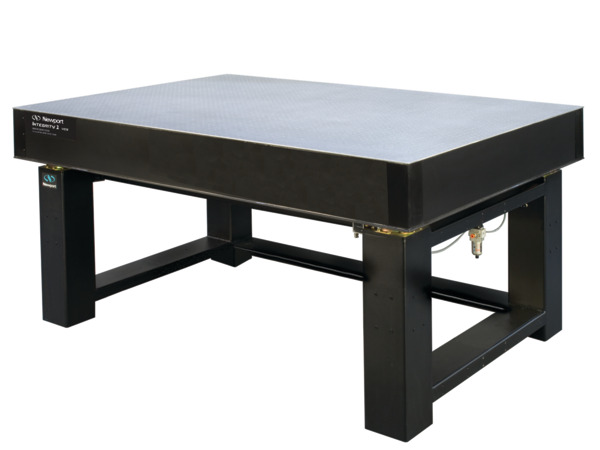 Table Systems |
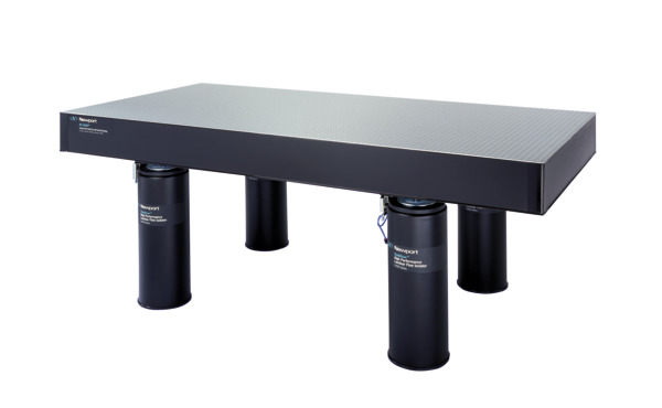 Tables and Legs |
|
|---|---|---|---|---|
| Dimension | Few feet | Few feet | Several feet, custom sizes | Several feet, custom sizes |
| Thickness | Few inches | Few inches | Several inches, custom thickness | Several inches, custom thickness |
| Portability | Must be carried or placed on "cart" | Casters on legs are standard | Larger, heavier, optional casters | Larger, heavier, optional casters |
| Isolation | None | ✓ | ✓ | ✓ |
| Damping | ✓ | ✓ | ✓ | ✓ |
| Setup | Base model comes assembled | Base model comes assembled | Support frame included but not assembled May need help from riggers |
Tables, legs sold separately May need help from riggers |
Resources
Advancing System-in-Package SiP Technology(7.3 MB, PDF)