Motorized Goniometer, ±45° Travel Range, Micro-step, M6, BGM200
Model: M-BGM200BPP

Product Series Overview
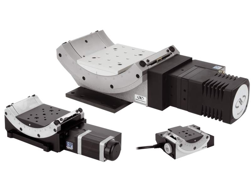
High Precision Stepper Motor GoniometersThe M-BGM200BPP Metric Goniometer features a worm mounted rotary encoder for improved accuracy and repeatability. The encoder also provides a method for detecting motor stalling, an important feature for applications with high loads or torques. This PP mini-step drive version enables high angular speeds up to 20°/sec .BG Series goniometric cradles rotate on a transverse axis above the platform. Compared to full 360° rotation stages, they offer maximum free access to the rotating part and allow construction of very compact multi-axis rotation assemblies. BG cradles are designed so that orthogonal mounting of two adjacent-size cradles (e.g., BGS50 and BGS80) provides two perpendicular rotational axes intersecting at about the same point in space. Mounting a rotation stage under the assembly adds a third orthogonal rotation axis through the same point. Precision rotation is ensured by a precision ground, hardened worm gear drive. Single row ball bearings and precision ground tool-steel races ensure smooth rotation with minimal wobble and eccentricity. A home switch, conveniently located at the center of travel, facilitates the return of the platform to a level position.
Precision Multi-Axis Assemblies
BG goniometers are designed so that two adjacent-sized models can be directly mounted orthogonally to each other (for example, BGS80 with BGM120) to pivot about the same point in space. The direct mounting capability saves set-up time, design time, and adapter plate costs. For additional rotation axes, a rotation stage can be mounted under the assembly or on the top BG platform. The video demonstrates an open access, multi-axis tip, tilt and rotation assembly with two BG goniometers and two rotation stages.
Open Rotation Platform
The BG series stages provide up to ±45° of transverse axis rotation enforced with mechanical limit switches. The stage is designed for maximum free access to the rotating platform, allowing for simplified stacking and mounting.

Precision Worm Gear Drive

Ball Bearings with Tool-Steel Races
Stepper Motor Versions
The PP and BPP mini-step drive versions are for applications that require higher speeds. For higher torque and vacuum applications, the PE and BPE full-step drive versions are recommended.


Resources & Downloads
Manuals
BG Goniometric Cradles User Manual 2(1.8 MB, PDF)
Related Products
Compatible Controllers
| Compare | Description | Drawings, CAD & Specs | Avail. | Price | ||
|---|---|---|---|---|---|---|
 | xps-d-universal-motion-controller1XPS-D Universal High-Performance 1-8 Axis Motion Controller and Driver | |||||
 | xps-rl-universal-high-performance-motion-controller2XPS-RLD Universal High-Performance 1-4 Axis Motion Controller and Driver | |||||
 | esp301-3-axis-dc-and-stepper-motion-controllerESP302 3-Axis DC and Stepper Motion Controller |
Notes:
- Requires XPS-DRV11 driver module
- Requires XPS-DRV11 driver module
Accessories
| Compare | Description | Drawings, CAD & Specs | Avail. | Price | ||
|---|---|---|---|---|---|---|
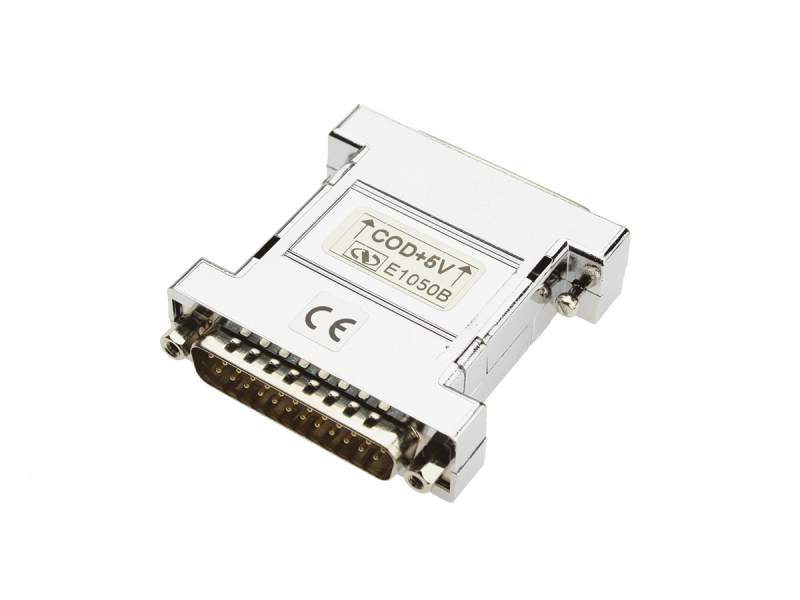 | MMCABLE-REGInline Regulator, 5 VDC, for MMCABLEs 5 m or longer | |||||
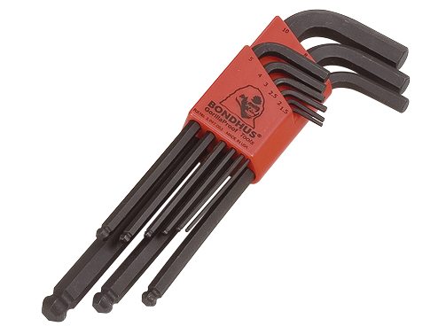 | M-FK-BLXL-Allen Wrench Set, Sizes: 1.5, 2, 2.5, 3, 4, 5, 6, 8, 10 mm, Metric | |||||
 | M-SK-M6ABlack Oxide Screw Kit, M6, Assortment, Qty 261 |
Similar
Frequently Purchased Together
| Compare | Description | Drawings, CAD & Specs | Avail. | Price | ||
|---|---|---|---|---|---|---|
| ESP302-2NMotion Controller & Driver, 2-Axis, Ethernet, RS232 |