DynamYX® 300 Wafer Positioning Air Bearing Stage
DynamYX® 300 Wafer Positioning Air Bearing Stage
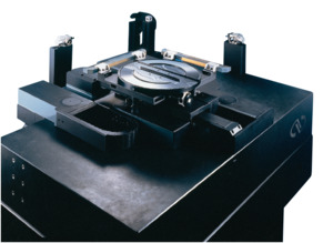
Designed for 300mm wafer test, measurement, and processing applications, the DynamYX® 300 Wafer Positioning Stage features a simple three-piece architecture in a two motor design that provides a cost effective solution for high accuracy and dynamic performance for step-and-settle and/or scanning applications.
- Designed for 300 mm wafer test, measurement & processing applications
- Acceleration: 0.75G X-Axis, 1.5G Y-Axis
- Velocity: 400mm/sec
- Repeatability: ±50nm (long term)
- Accuracy: 0.4µm
- Travel Range: 520mm by 340mm See All Features
| Compare | Description | Drawings, CAD & Specs | Avail. | Price | ||
|---|---|---|---|---|---|---|
 | DYNAMYX300Air Bearing Stage, Wafer Positioning, DynamYX® 300 |
Features
DynamYX Family of Air-bearing Stages
Position Feedback
The positioning loop on DynamYX may be closed using a single linear encoder for each axis. As shown in the adjacent illustration, the encoder measuring positions are closely located to the substrate’s surface reducing the already minimal abbe offset affect. For the X-axis, the linear scale is typically mounted to the underside of the bridge structure with the read-head in-line with the system’s optical path and affixed to the moving ceramic guide. System architectures that do not allow this configuration can be accommodated by mounting the X-axis scale to a supplementary SiC spar located at the rear side of the system. The Y-axis has its scale mounted to a small SiC bracket on the moving carriage. The read head is fixed to the arm of the L-shape structure. Read-heads which have fixed positions relative to the tool’s optical path are beneficial in optimizing precision. With an encoder signal period of 2mm, resolutions down to 0.1nm are possible with Newport’s XPS or SPS controllers each with internal 20,000 times interpolation. Equipped with linear encoders the DynamYX is an extremely accurate and very repeatable platform allowing for very high accuracy through error mapping. The geometric stability of the ceramic elements of these stages results in systems that can be mapped once at our factory then, upon installation, only require a simple length calibration to compensate for uniform thermal expansion. For applications where the accuracy requirements exceed the capabilities of error compensation, or in certain scanning modes where the absolute position of the stage must be the basis of a very precise trigger or latch, linear encoders must yield to laser interferometers which are also part of our offering.
Chuck Interface
Resources
Literature
Technical Articles
Bringing Hybrid Bonding Into Production(1.9 MB, PDF)