Optical Receiver Selection Guide
Overview
As the interface from a photonics experiment to electronic instruments, photodetection is critical to extracting and preserving experimental results. Newport's optical receivers and detectors make photodetection easy and provide the lowest noise and cleanest response possible. Our broad offering spans wavelength ranges from UV to short-wave IR for free-space and fiber-coupled configurations in many versions: high-speed, general-purpose, balanced, ultralow-light-level and large-area. There are many considerations in selecting an optical receiver or detector, and the features described here and listed in the tables below are intended to help with the process.
Plug & Play
Just flip a switch on Newport's optical receivers and detectors to see your results, even with our ultrahigh-speed devices. With built-in amplifiers, driver electronics, adjustable gain and filter settings, and LabVIEW™ compatibility, our optical receivers and detectors simplify the chores associated with the electronic portion of your photonics experiment. So as an optical engineer, you won't also have to become a microwave engineer to achieve the results you want.
Receiver or Detector?
Both types of modules employ a photodiode to convert optical signals to electrical signals. The difference between a photoreceiver and photodetector is amplification. With photoreceivers, the photodiode is followed by a low-noise, linear, high-bandwidth amplifier. Characteristics of amplified photoreceivers include usability at low optical power levels (hundreds of nW), high dynamic range and isolation of the photodiode from external circuits. On the other hand, typical non-amplified photodetector features include usability at optical ranges of hundreds of mW, the ability to be battery-biased, simplified internal circuit design for less noise and, compared to a similar photoreceiver, lower cost.
3-dB Bandwidth
An important property of optical receivers and detectors is the 3-dB bandwidth, which is defined by the frequency at which the output response drops to 50% of its value at DC or other low frequency reference. Newport's optical receiver and detector product series are grouped according to their 3-dB bandwidths.
Conversion Gain
The sensitivity of an optical receiver or detector – i.e., how much output voltage will result from a given optical input power – is known as the conversion gain, measured in Volts/Watt. In an amplified photoreceiver, conversion gain is the product of the detector's responsivity, the amplifier's gain and the input impedance. In a non-amplified photodetector, the conversion gain is the product of the responsivity and load impedance. Gain can be either positive or negative, so an external inverting function may be used if desired.
Rise Time
The fastest transition that can be measured is called the rise time. In general, it is the 10% to 90% transition time (rise time) of the output response when the detector is illuminated by a negligibly short optical step function. Rise time is the parameter of choice when measuring either rising or falling edges. This type of measurement is especially common in digital communications systems where bit streams are comprised of an endless series of rising and falling edges. The rise time of a detector should be at least three times shorter than the rise time you expect to measure.
Broadest Selection
With a wide variety of standard, custom, and OEM versions, we have the broadest selection of plug-&-play photoreceivers and photodetectors available anywhere. Spanning the UV to IR with beam-positioning, balanced, ultralow-light-level, large-area, high-speed and general-purpose versions in free-space and fiber-coupled configurations, Newport is the place to find the right photoreceiver and photodetector for your needs.
Browse all Photoreceivers to review our standard models, or select a specific product series below to learn more about our products and capabilities. We also offer a complete line of Optical Power and Energy Meters.
Fiber-Optic Receivers
These amplified high-speed fiber-optic receivers offer bandwidths up to 38 GHz for receiving fiber-optic data while delivering the lowest noise and cleanest responses possible. The product series shown below are compatible with both single-mode and multi-mode fiber coupling.
| Series | Wavelength Ranges (nm) |
Peak Conversion Gain (V/W) |
Rise Time (ps) |
Detector Material |
|---|---|---|---|---|
 22 GHz and 38 GHz Fiber-Optic Receivers |
630-1620 630-865 800-865 |
-65 -70 |
12.5 16.5 |
GaAs InGaAs |
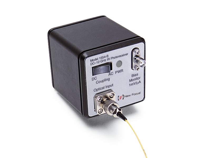
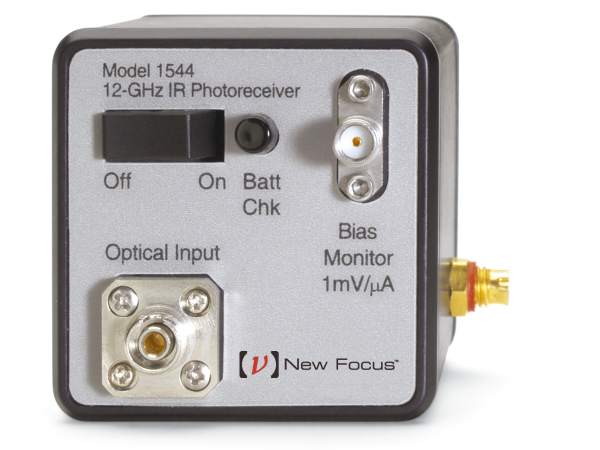 12 GHz Fiber-Optic Receivers |
500-1630 780-870 780-1630 |
-900 -800 -700 -450 |
32 | GaAs InGaAs |
 10 GHz Battery Biased Fiber-Optic Receivers |
500-890 1475-2100 |
970 2350 |
35 | GaAs InGaAs |
 1 GHz AC Coupled Fiber-Optic Receivers |
320-1000 900-1700 |
350 700 |
400 | Si InGaAs |
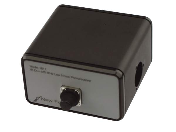 125 MHz Fiber-Optic Receivers |
320-1000 900-1700 |
4 x 10⁴ | 3000 | Si InGaAs |
 10 MHz Adjustable Fiber-Optic Receivers |
300-1050 900-1700 |
9.2 x 10⁶ 18.4 x 10⁶ |
8 x 10⁴ | Si InGaAs |
 200 kHz Fiber-Optic Receivers |
300-1050 900-1700 |
9.4 x 10⁶ 18.8 x 10⁶ |
2 x 10⁶ | Si InGaAs |
Free Space Optical Receivers
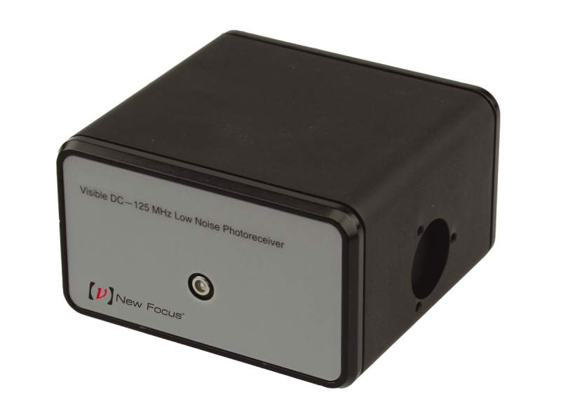
These amplified free-space photoreceivers offer bandwidths up to 10 GHz for detecting high-speed free space optical signals with the lowest noise and cleanest responses possible.
| Series | Wavelength Ranges |
Peak Conversion Gain (V/W) |
Rise Time (ps) |
Detector Diameter (mm) |
Detector Material |
|---|---|---|---|---|---|
 1.2 to 10 GHz Biased AC Coupled Optical Receivers |
300-1100 500-900 1000-1600 1000-1650 1475-2100 |
450-3250 | 35 400 500 |
0.032-0.4 | Si GaAs InGaAs |
 1 GHz AC Coupled Optical Receivers |
320-1000 900-1700 |
350 700 |
400 | 0.1 0.4 |
Si InGaAs |
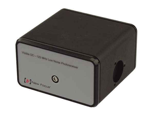 125 MHz Optical Receivers |
320-1000 900-1700 |
4 x 10⁴ | 3000 | 0.3 0.4 |
Si InGaAs |
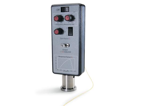
10 MHz Adjustable Optical Receivers |
300-1050 900-1700 |
9.2 x 10⁶ 18.4 x 10⁶ |
8 x 10⁴ | 0.3 0.9 |
Si InGaAs |
 200 kHz Optical Receivers/a> |
300-1050 900-1700 |
9.4 x 10⁶ 18.8 x 10⁶ |
2 x 10⁶ | 0.3 0.9 |
Si InGaAs |
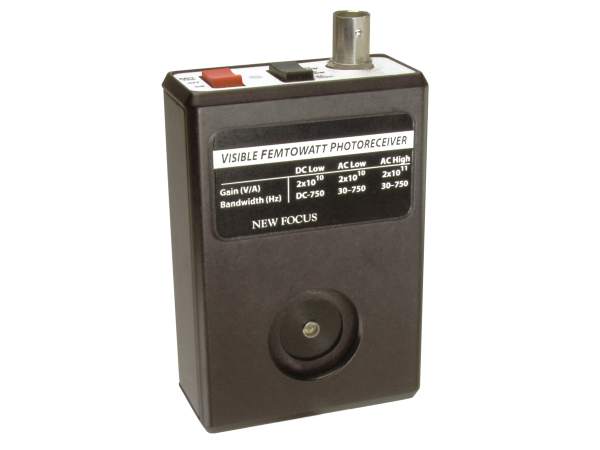 750 Hz Femtowatt Photoreceivers |
320-1050 800-1700 |
1 x 10¹¹ 2 x 10¹¹ |
1 | Si InGaAs |
Balanced Photoreceivers
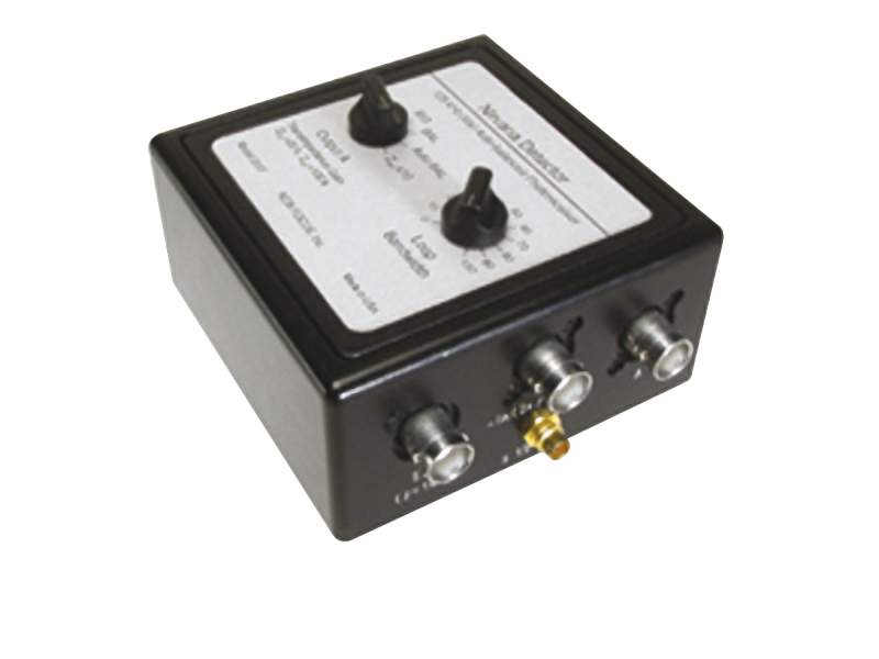
For applications that require detection of a weak or small signal from a noisy background, such as absorption spectroscopy or heterodyne detection, balanced photoreceivers are ideal. Consisting of two well-matched optical inputs, balanced photoreceivers amplify difference-mode signals and cancel common-mode signals, hence extracting the desired signal and removing noise. Newport's balanced photoreceivers series include models that are compatible with fiber-optic or free space optical signals.
| Series | Wavelength Ranges |
Peak Conversion Gain (V/W) |
Rise Time (ps) |
Detector Diameter (mm) |
Detector Material |
|---|---|---|---|---|---|
 Nirvana™ Auto-Balanced Optical Receivers |
400-1070 800-1700 900-1650 |
3 x 10⁴ 5.2 x 10⁵ 1 x 10⁶ |
3000 3 x 10⁶ |
FC/APC 1 2.5 |
Si InGaAs |
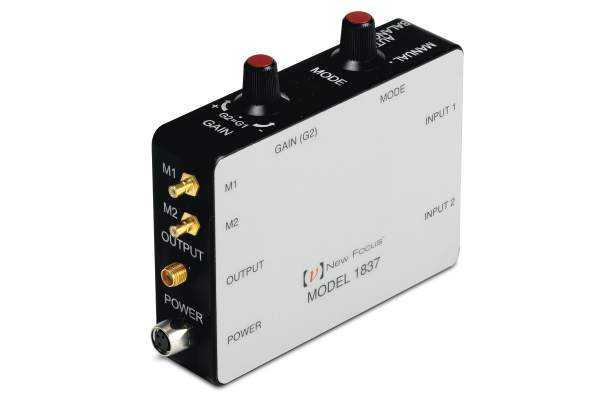
 650 and 800 MHz Balanced Optical Receivers |
320-1000 900-1700 |
350 700 |
800 | FC 0.1 0.4 |
Si InGaAs |
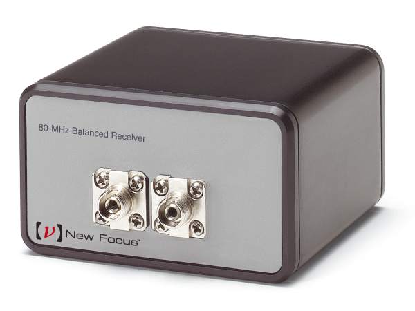 80 MHz Balanced Optical Receivers |
320-1000 900-1700 |
2 x 10⁴ 4 x 10⁴ |
3000 | FC FC/UPC 0.1 0.4 |
Si InGaAs |
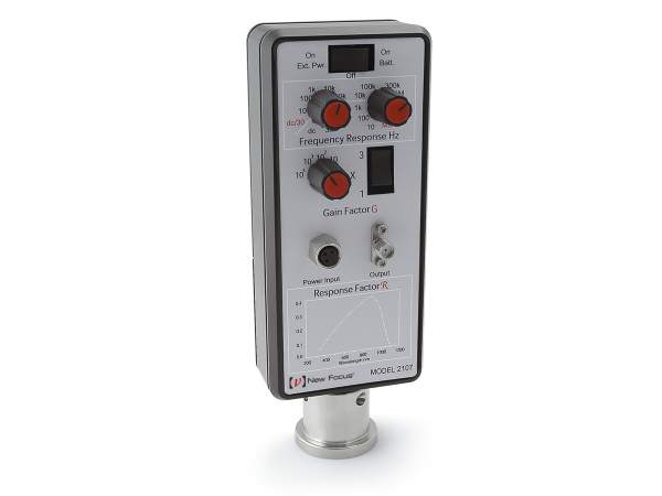 10 MHz Adjustable Gain and Bandwidth Balanced Optical Receivers |
300-1070 900-1700 |
9.2 x 10⁶ 18.4 x 10⁶ |
8 x 10⁴ | FC 0.3 0.9 |
Si InGaAs |
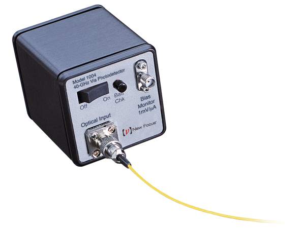
Fiber-Optic Detectors
These non-amplified fiber-optic detectors use special photodiodes with high speed electronic circuits to convert fast pulses in optical fibers to electrical signals for measurement.
| Series | Wavelength Ranges (nm) |
Peak Conversion Gain* (V/W) |
Rise Time (ps) |
Fiber Couping Type | Detector Material |
|---|---|---|---|---|---|
 45 GHz Fiber-Optic Detector |
500-1630 | 10 | 9 | Single-mode | InGaAs |
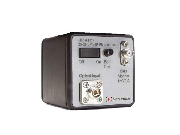 25 GHz Fiber-Optic Detectors |
500-1630 850-1630 |
11 17 |
14 | Single-mode Multi-mode |
InGaAs |
 Battery Biased Fiber-Optic Detectors |
500-900 830-2150 1000-1650 |
0.45-0.95 A/W Responsivity | 16-30 | Single-mode | GaAs InGaAs |
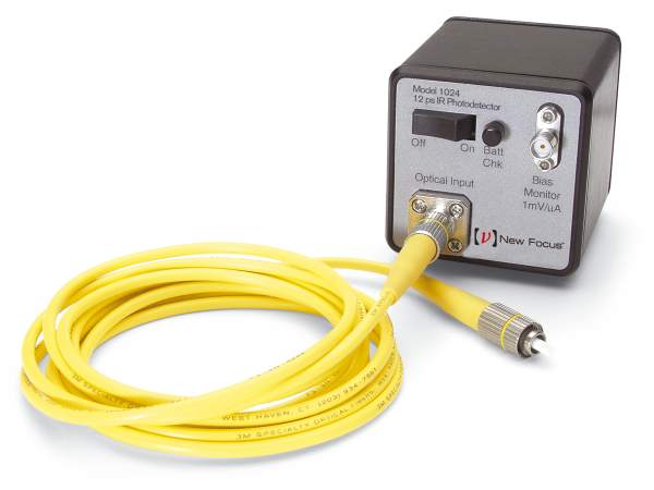 Time Domain Fiber-Optic Detectors |
500-1630 850-1630 |
10 11 15 |
12 18.5 |
Single-mode Multi-mode |
InGaAs |
Free Space Optical Detectors
These non-amplified free space detectors convert fast pulses of free space optical signals to electrical signals for measurement.
| Series | Wavelength Ranges |
Peak Conversion Gain* (V/W) |
Rise Time (ps) |
Detector Diameter (mm) |
Detector Material |
|---|---|---|---|---|---|
 Biased Free Space Optical Detectors |
200-1100 300-1100 350-1100 500-890 800-1800 830-2150 1000-1600 1000-1650 |
0.47-1.3 A/W Responsivity | 3-300 | 0.02-4.57 | Si GaAs InGaAs |
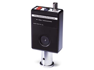 Nanosecond Free Space Optical Detectors |
350-1000 | 28 | 1 | 0.8 | Si |
Optical Receiver Finder
Quickly find the most appropriate high speed detectors or receivers for your application by selecting any of the key parameters from below. Please note that a photoreceiver device type is defined as a photodetector with an amplifier, which results in a higher sensitivity in the signal detection. Also note that the detector material is the key parameter that dictates the wavelength range.
| Product Description | Wavelength Range | Maximum Conversion Gain | 3 dB Bandwidth | Rise Time | ||
|---|---|---|---|---|---|---|
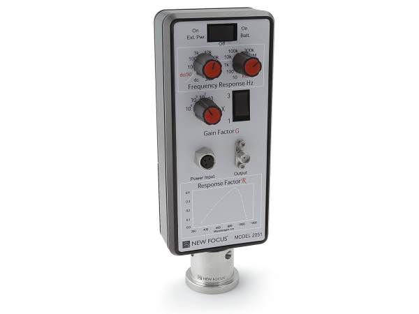
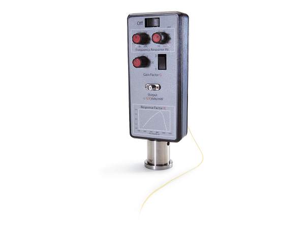
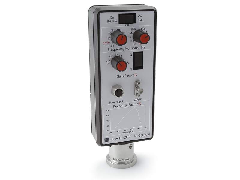 | 2051-FS-MAdjustable Optical Receiver, 300-1050 nm Silicon Detector, 10 MHz, M4 | 300-1050 nm | 9.2x10⁶ V/W | 10 MHz, 5 MHz, 150 kHz | 80 ns | |
 | 1811-FS-ACFree Space Optical Receiver, 900-1700 nm InGaAs, 25 kHz - 125 MHz, AC-Coupled | 900-1700 nm | 4x10⁴ V/W | 25 kHz to 125 Mhz | 3 ns | |
 | 1623Nanosecond Photodetector, 800-1700 nm, 0.1 mm InGaAs Detector, 1 ns | 800-1700 nm | DC to 500 MHz | 1 ns | ||
 | 818-BB-30AOptical Receiver, AC coupled, 1000-1600 nm Biased InGaAs Detector, 1.5 GHz | 1000-1600 nm | 900 V/W at 1300 nm | 400 ps | ||
| 2053-FS-MAdjustable Optical Receiver, 900-1700 nm InGaAs Detector, 10 MHz, M4 | 900-1700 nm | 18.4 x 10⁶ V/W | 10 MHz, 5 MHz, 150 kHz | 80 ns | |
 | 2017Auto-balanced Optical Receiver, Nirvana, 800-1700 nm, 125 kHz, 8-32 / M4 | 800-1700 nm | 1 x 10⁶ V/W | DC to 125 KHz | 3 µs | |
 | 1607-AC-FSBalanced Optical Receiver, Silicon, 320-1000 nm, 650 MHz, Free Space | 320-1000 nm | 350 V/W | 40 kHz to 650 MHz | 800 ps | |
 | 2001-FS-MOptical Receiver, Silicon, 300-1050 nm, 200 kHz Bandwidth, M4 | 300-1050 nm | 9.4x10⁶ V/W | DC to 200 kHz | 2 µs | |
 | 1807-FSBalanced Optical Receiver, 320-1000 nm Silicon Detector, 80 MHz, Free Space | 320-1000 nm | 2 x 10⁴ V/W | DC to 80 MHz | 3 ns | |
 | 2117-FS-MAdjustable Balanced Receiver, 800-1700 nm, 10 MHz, Free Space, M4 | 900-1700 nm | 18.4 x 10⁶ V/W | 10 MHz, 5 MHz, 150 kHz | 80 ns | |
| 1817-FSBalanced Optical Receiver, 900-1700 nm InGaAs Detector, 80 MHz, Free Space | 900-1700 nm | 4 x 10⁴ V/W | DC to 80 MHz | 3 ns | |
| 2001-FC-MFiber-Optic Receiver, 300-1050 nm Silicon Detector, 200 kHz, FC/PC, M4 | 300-1050 nm | 9.4x10⁶ V/W | DC to 200 kHz | 2 µs | |
| 1607-AC-FCBalanced Fiber-Optic Receiver, Silicon, 320-1000 nm, 650 MHz, FC Connector | 320-1000 nm | 350 V/W | 40 kHz to 650 MHz | 800 ps | |
| 1617-AC-FSBalanced Optical Receiver, InGaAs, 900-1700 nm, 800 MHz, Free Space | 900-1700 nm | 700 V/W | 40 kHz to 800 MHz | 800 ps | |
| 2051-FC-MFiber-Optic Receiver, Adjustable, 300-1050 nm Silicon Detector, 10 MHz, M4 Thread | 300-1050 nm | 9.4x10⁶ V/W | 10 MHz, 5 MHz, 150 kHz | 80 ns | |
 | 818-BB-31FC Bulkhead High Speed Photodetector, 1000-1600 nm Battery Biased InGaAs Detector, 2 GHz | 1000-1600 nm | DC to 2 GHz | 175 ps | ||
| 1617-AC-FCBalanced Fiber-Optic Receiver, InGaAs, 900-1700 nm, 800 MHz, FC Connector | 900-1700 nm | 700 V/W | 40 kHz to 800 MHz | 800 ps | |
| 1817-FCBalanced Fiber-Optic Receiver, 900-1700 nm InGaAs Detector, 80 MHz | 900-1700 nm | 4 x 10⁴ V/W | DC to 80 MHz | 3 ns | |
| 2117-FCBalanced Fiber-Optic Receiver, Adjustable, 800-1700 nm, 10 MHz, 8-32 [Phase out] | 900-1700 nm | 18.4 x 10⁶ V/W | 10 MHz, 5 MHz, 150 kHz | 80 ns | |
| 2107-FC-MBalanced Fiber-Optic Receiver, Adjustable, 320-1000 nm, 10 MHz, M4 | 300-1070 nm | 9.2 x 10⁶ V/W | 10 MHz, 5 MHz, 150 kHz | 80 ns | |
| 2107-FCBalanced Fiber-Optic Receiver, Adjustable, 320-1000 nm, 10 MHz, 8-32 [Phase out] | 300-1070 nm | 9.2 x 10⁶ V/W | 10 MHz, 5 MHz, 150 kHz | 80 ns | |
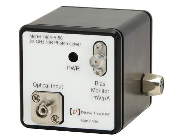
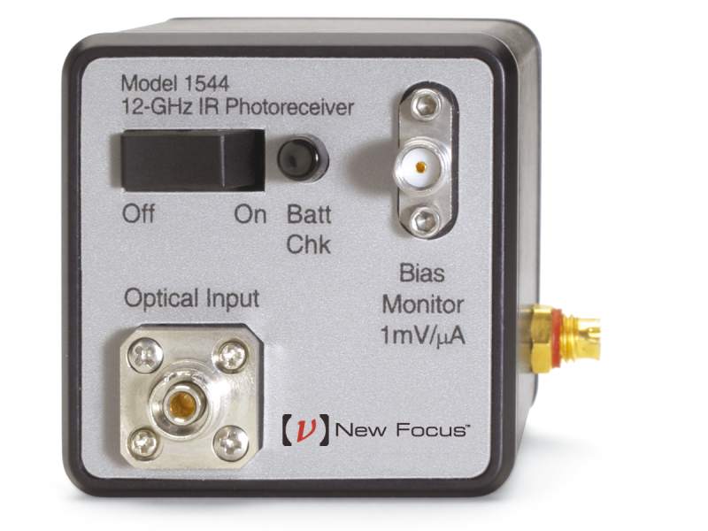 | 1544-A-50Fiber-Optic Receiver, NIR, 12 GHz, FC Multimode | 800-1650 nm | -700 V/W | 10 kHz to 12 GHz | 32 ps | |
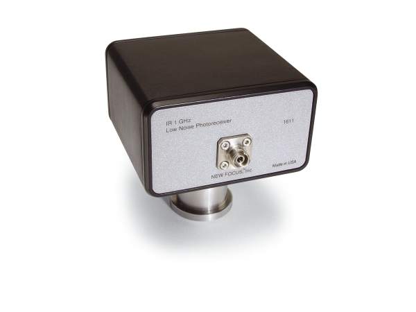
 | 1611FS-ACFree Space Optical Receiver, 900-1700 nm InGaAs, 30 kHz to 850 MHz, AC-Coupled | 900-1700 nm | 700 V/W | 30 kHz to 850 MHz | 400 ps | |
| 1601FS-ACFree Space Optical Receiver, 320-1000 nm Silicon, 30 kHz to 1 GHz, AC-Coupled | 320-1000 nm | 350 V/W | 30 kHz to 1 GHz | 400 ps | |
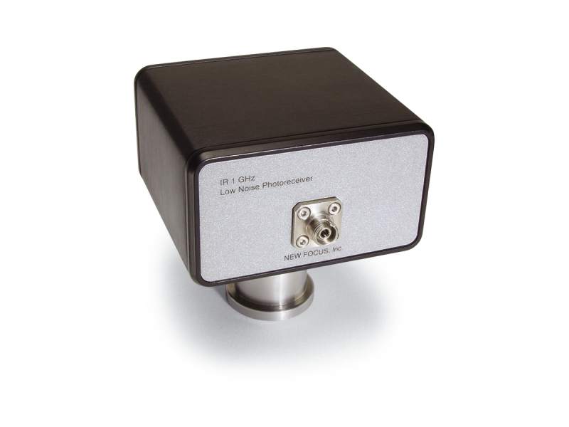 | 1601FC-ACFiber-Optic Receiver, 320-1000 nm Silicon, 30 kHz to 1 GHz, FC/PC, AC-Coupled | 320-1000 nm | 350 V/W | 30 kHz to 1 GHz | 400 ps | |
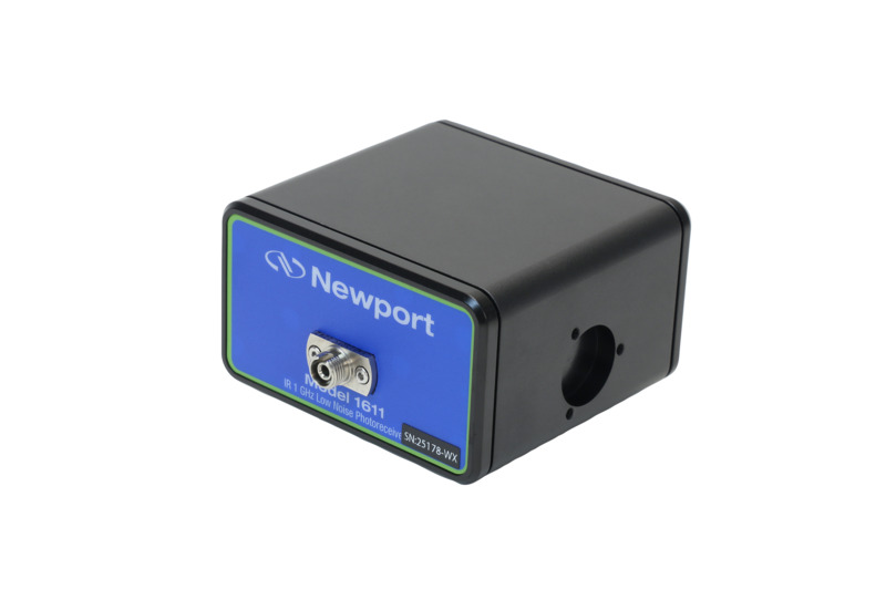 | 1611FC-ACFiber-Optic Receiver, 900-1700 nm InGaAs, 30 kHz to 850 MHz, FC/PC, AC-Coupled | 900-1700 nm | 700 V/W | 30 kHz to 850 MHz | 400 ps | |
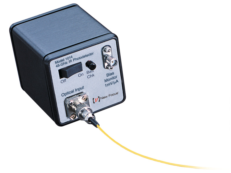 | 1014Ultrafast Fiber-Optic Biased Detector, 500-1630 nm InGaAs, 45 GHz, FC Singlemode | 500-1630 nm | 10 V/W | DC to 45 GHz | 9 ps | |
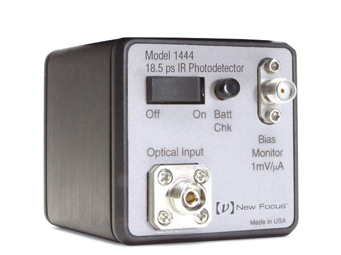 | 1444Fiber-Optic Detector, Time Domain, 500-1630 nm, 18.5 ps, FC Singlemode | 500-1630 nm | 15 V/W | DC to 20 GHz | ||
 | 1544-B-50Fiber-Optic Receiver, DC-Coupled, 800-1650 nm, 12 GHz, FC Multimode | 800-1650 nm | -700 V/W | DC to 12 GHz | 32 ps | |
 | 1801-FCFiber-Optic Receiver, 320-1000 nm Silicon, 125 MHz, FC, DC-Coupled | 320-1000 nm | 2x10⁴ V/W | DC to 125 MHz | 3 ns | |
| 2053-FC-MFiber-Optic Receiver, Adjustable, 900-1700 nm InGaAs Detector, 10 MHz, M4 Thread | 900-1700 nm | 18.8x10⁶ V/W | 10 MHz, 5 MHz, 150 kHz | 80 ns | |
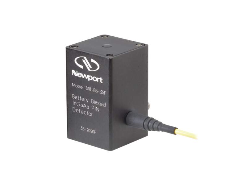 | 818-BB-35FFiber-Optic Detector, 1000-1650 nm Battery Biased InGaAs Detector, 15 GHz, FC/UPC | 830-1650 nm | DC to 15 GHz | 25 ps | ||
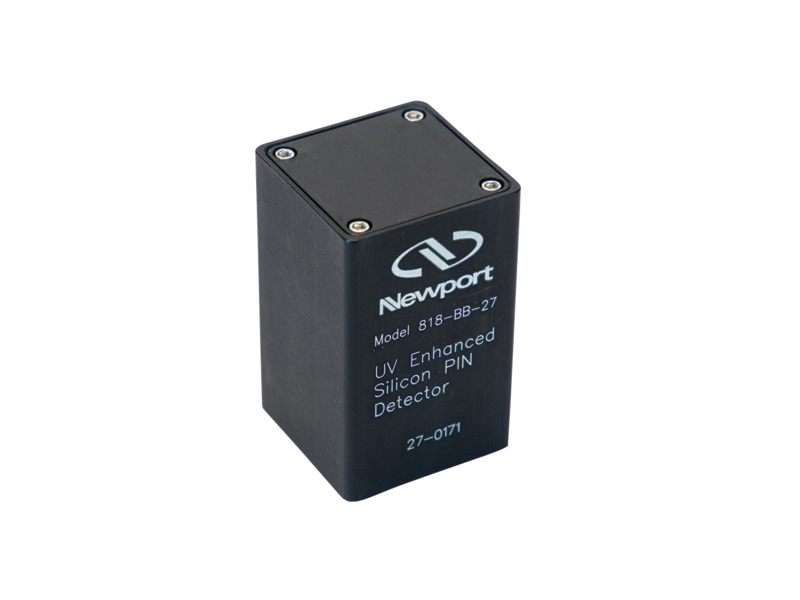 | 818-BB-27High Speed Photodetector, 200-1100 nm UV-Silicon Detector, 118 MHz | 200-1100 nm | DC to 118 MHz | 3 ns | ||
| 1807-FCBalanced Fiber-Optic Receiver, 320-1000 nm Silicon Detectors, 80 MHz | 320-1000 nm | 2 x 10⁴ V/W | DC to 80 MHz | 3 ns | |
 | 1024Fiber-Optic Detector, Time Domain, 500-1630 nm, 12 ps, FC Singlemode | 500-1630 nm | 10 V/W | DC to 26 GHz | ||
 | 1414Fiber-Optic Detector, 500-1630 nm, 25 GHz, FC Singlemode | 500-1630 nm | 17 V/W | DC to 25 GHz | 14 ps | |
| 1444-50Fiber-Optic Detector, Time Domain, 850-1630 nm, 18.5 ps, FC Multimode | 850-1630 nm | 14 V/W | DC to 20 GHz | ||
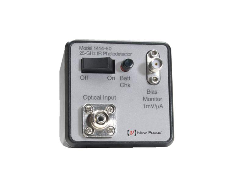 | 1414-50Fiber-Optic Detector, High Speed, 850-1630 nm, 25 GHz, FC 50 µm Multimode | 850-1630 nm | 11 V/W | DC to 25 GHz | 14 ps | |
| 2011-FS-MOptical Receiver, 900-1700 nm InGaAs Detector, 200 kHz Bandwidth, M4 | 900-1700 nm | 18.8x10⁶ V/W | DC to 200 kHz | 2 µs | |
| 1544-AFiber-Optic Receiver, NIR, 12 GHz, 800-1650 nm, FC Singlemode | 800-1650 nm | -800 V/W | 10 kHz to 12 GHz | 32 ps | |
| 1544-BFiber-Optic Receiver, DC Coupled, 800-1650 nm, 12 GHz, FC Singlemode | 800-1650 nm | -800 V/W | DC to 12 GHz | 32 ps | |
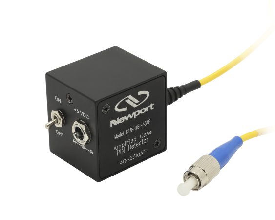
 | 818-BB-45FFiber-Optic Detector, 500-900 nm Battery Biased GaAs Detector, 12.5 GHz, FC/UPC | 500-890 nm | DC to 12.5 GHz | 30 ps | ||
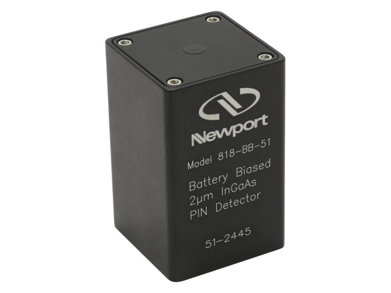 | 818-BB-51High Speed Photodetector, 830-2150 nm Battery Biased Extended InGaAs Detector, 10 GHz | 830-2150 nm | DC to 10 GHz | 28 ps | ||
| 1580-BFiber-Optic Receiver, DC Coupled, 780-870 nm, 12 GHz, FC Multimode. | 780-870 nm | -450 V/W | DC to 12 GHz | 32 ps | |
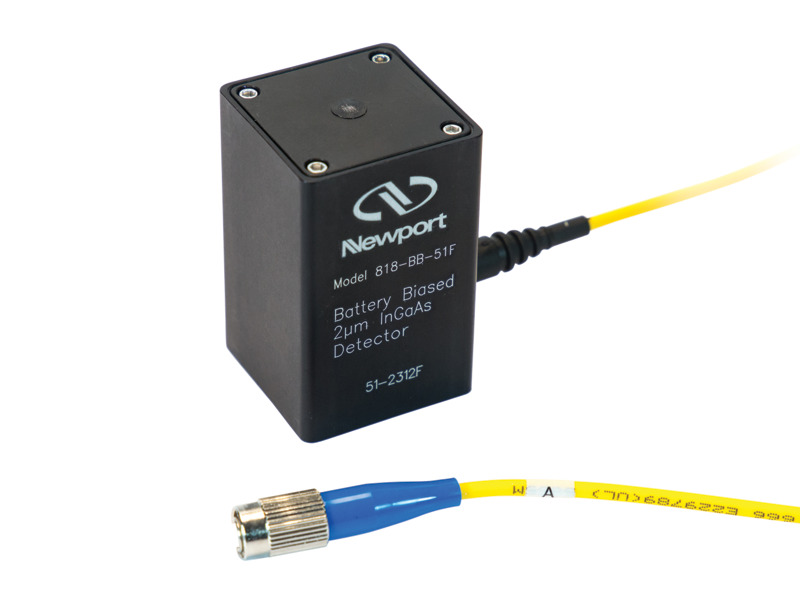 | 818-BB-51FFiber-Optic Detector, 830-2150 nm Battery Biased Extended InGaAs, 10 GHz, FC/UPC | 830-2150 nm | DC to 10 GHz | 28 ps | ||
 | 818-BB-30High Speed Photodetector, 800-1750 nm Battery Biased InGaAs Detector, 2 GHz | 800-1750 nm | DC to 2 GHz | 175 ps | ||
 | 818-BB-45High Speed Photodetector, 500-890 nm Battery Biased GaAs Detector, 12.5 GHz | 500-890 nm | DC to 12.5 GHz | 30 ps | ||
 | 1811-FCFiber-Optic Receiver, 900-1700 nm InGaAs, 125 MHz, FC, DC-Coupled | 900-1700 nm | 4x10⁴ V/W | DC to 125 MHz | 3 ns | |
| 1621Nanosecond Photodetector, 350-1000 nm, 0.8 mm Silicon Detector, 1 ns | 350-1000 nm | DC to 500 MHz | 1 ns | ||
| 1801-FC-ACFiber-Optic Receiver, 320-1000 nm Silicon, 25 kHz to 125 MHz, FC, AC-Coupled | 320-1000 nm | 2x10⁴ V/W | 25 kHz to 125 MHz | 3 ns | |
| 1801-FSFree Space Optical Receiver, 320-1000 nm Silicon, 125 MHz, DC-Coupled | 320-1000 nm | 2x10⁴ V/W | DC to 125 MHz | 3 ns | |
 | 818-BB-35High Speed Photodetector, 1000-1650 nm Battery Biased InGaAs Detector, 15 GHz | 830-1650 nm | DC to 15 GHz | 25 ps | ||
| 1811-FC-ACFiber-Optic Receiver, 900-1700 nm InGaAs, 25 kHz to 125 MHz, FC, AC-Coupled | 900-1700 nm | 4x10⁴ V/W | 25 kHz to 125 MHz | 3 ns | |
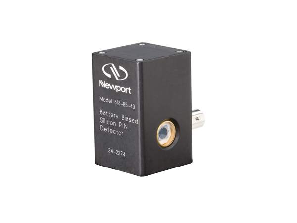
 | 818-BB-40High Speed Photodetector, 300-1100 nm Biased Silicon Detector, 25 MHz | 350-1100 nm | DC to 25 MHz | 30 ns | ||
| 1801-FS-ACFree Space Optical Receiver, 320-1000 nm Silicon, 25 kHz - 125 MHz, AC-Coupled | 320-1000 nm | 2x10⁴ V/W | 25 kHz to 125 Mhz | 3 ns | |
| 2051-FSAdjustable Optical Receiver, 300-1050 nm Silicon Detector, 10 MHz, 8-32. | 300-1050 nm | 9.2x10⁶ V/W | 10 MHz, 5 MHz, 150 kHz | 80 ns | |
| 2053-FSAdjustable Optical Receiver, 900-1700 nm InGaAs Detector, 10 MHz, 8-32 [Phase out] | 900-1700 nm | 18.4 x 10⁶ V/W | 10 MHz, 5 MHz, 150 kHz | 80 ns | |
| 2117-FC-MBalanced Fiber-Optic Receiver, Adjustable, 800-1700 nm, 10 MHz, M4 | 900-1700 nm | 18.4 x 10⁶ V/W | 10 MHz, 5 MHz, 150 kHz | 80 ns | |
| 2117-FSAdjustable Balanced Receiver, 800-1700 nm, 10 MHz, Free Space [Phase out] | 900-1700 nm | 18.4 x 10⁶ V/W | 10 MHz, 5 MHz, 150 kHz | 80 ns | |
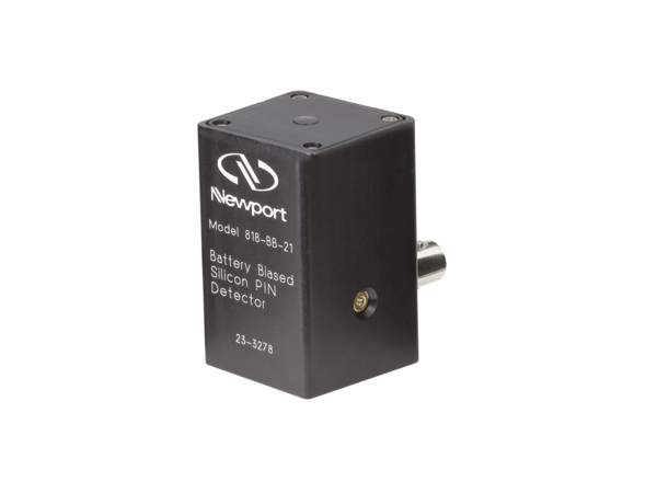
 | 818-BB-21High Speed Photodetector, 300-1100 nm Battery Biased Silicon Detector, 1.2 GHz | 300-1100 nm | DC to 1.2 GHz | 300 ps |
Accessories
| Description | Features | |||
|---|---|---|---|---|
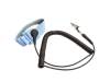
 | Photodetector and Photoreceiver Power Supply |
| | |
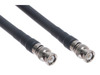
 | 40 GHz Flexible Cable |
| | |
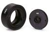 | Filter Holder and Fiber Adapter |
| | |
 | | |||
 | |